1 689 975 197 (2006-09-22)
Robert Bosch GmbH
en
18
ACS 500
459790-1
0
6
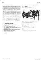
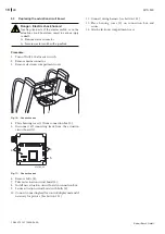
Fig. 14: Control and display unit
8. Disconnect connecting lead (6) from control/display
unit.
459786-14
6
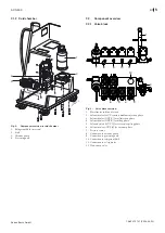
Fig. 15: Scale
9. Remove complete scale (7) from the ACS 500.
8
459786-17
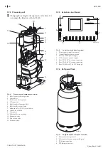
Fig. 16: Force sensor
10. Replace force sensor (8) with a new one.
11. Insert scale in mounting holes in ACS 500 and secure.
12. Connect connecting lead for force sensor to control and
display unit.
13. Secure connecting lead with cable tie.
14. Calibrate force sensor (see section 6.1.1).
15. Place refrigerant flask on scale.
16. Secure refrigerant flask with bolt (see Fig. 13, 1).
17. Remove coarse residue of pipe sealant on connecting
thread of refrigerant flask for the hose lines and clean
with a suitable cleaning medium (e. g. brake cleaner).
18. Apply a thin layer of pipe sealant to the refrigerant flask
connecting thread.
19. Connect hose lines.
20. Open stop cocks (see Fig. 13, 2) and shut-off valves
(see Fig. 13, 4) on refrigerant flask.
21. Attach electronic compartment and cold chamber
covers.

