


1 689 975 197 (2006-09-22)
Robert Bosch GmbH
en
0
ACS 500
459790-1
3
11
12
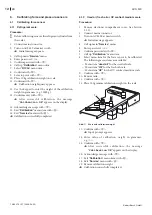
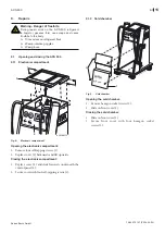
Fig. 20: Pipe union
14. Apply a thin layer of pipe sealant to the pipe union
thread (11 and 12).
15. Slide hose lines (5, 6 and 9 - See Fig. 18).
16. Slide hose lines (3 and 4) with union nuts onto pipe
union and secure.
17. Connect hose line (7) to HP connection (red) on
refrigerant flask.
18. Secure valve block with hexagon bolts and washers.
19. Connect connector to solenoid valves (see section
12.2.1).
20. Connect pressure sensor connecting lead to control/
display unit (see section 12.1).
21. Open stop cocks and shut-off valves on the refrigerant
flask.
22. Attach covers.
23. Calibrate pressure sensor (see section 6.2).
9.6
Replacing the pressure sensor
Procedure:
1. Turn off ACS 500 at master switch.
2. Remove mains connector.
3. Remove electronic compartment cover.
4. Dismantle valve block (see section 9.5).
459786-2
8
1
2
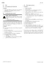
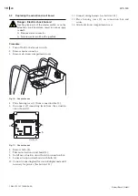
Fig. 21: Pressure sensor removal
5. Screw out pressure sensor (2).
6. Apply a thin layer of pipe sealant to the screw thread for
the new pressure sensor.
7. Screw the pressure sensor into the valve block (1).
8. Install valve block (see section 9.5).
9. Calibrate pressure sensor (see section 6.2).


