background image

16992000121

2014-11-07

Robert Bosch GmbH

10  |  MTS 6513 VCI  |  Getting Started

en

en

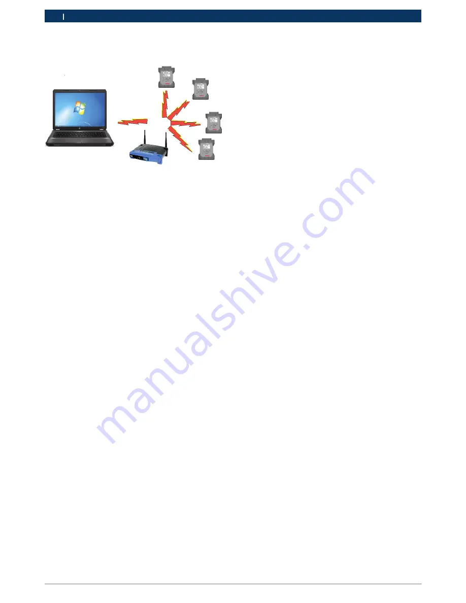
The illustration below shows several VCIs connected to 
a single laptop PC using a wireless access point.

Use the following procedure to configure your VCI for 
wireless communication in your environment. Before 
modifying the VCI communications interface, contact 
your IT Administrator.

1. 

Start the VCI Manager software by clicking on the 
VCI Manager icon.

2. 

Wait for the USB driver to be automatically configu-
red during the first time the USB dongle is inserted 
in the PC USB Port. 
 
Power Up the VCI by connecting the VCI to the 
vehicle DLC. 
 
Note, powering the VCI using the USB cable only 
does not supply enouh voltage to run the WiFi 
Dongle. 
 
Allow the VCI to boot completely.

3. 

Start the VCI Manager software by double-clicking 
the icon on the PC desktop.

4. 

The VCI icon in the VCI Explorer tab should now 
have a USB connection symbol displayed on top 
of the VCI icon. (See chart in section 8.4 for an ex-
ample of what the the USB symbol should look like 
as well as other icons that could be displayed). 
 
The USB icon indicates the PC is connected to 
the VCI via the USB cable. You can also move your 
mouse over the VCI icon in the VCI Explorer tab and 
bubble help will display how the VCI is connected 
to the PC.

5. 

Select the VCI with Green bars in the VCI Manager 
Explorer tab and click the <connect> button. -> 
Once connected, a green check mark will replace 
the green bars. The green check mark confirms the 
VCI is communicating P-to-P with the PC.  Once 

connected, select the Disconnect button and close 
the VCI Manager application.

6. 

Select the Network Setup tab.

7. 

Select the Wireless tab.

8. 

Select the Enable Wireless Interface check box in 
the Interface Control section. Once you enable the 
interface, the IP Address Configuration box and the 
Apply and Cancel buttons become active.

9. 

Select Obtain an IP address automatically if your 
LAN automatically assigns IP addresses. Otherwise 
enter the assigned IP Address and Subnet mask 
given to you by your IT Administrator.

10. 

Select Access Point to begin wireless access point 
configuration.

11. 

Specify the network name:


i

If you are not within range of the access point you 
will use, select the Enter Network Name [SSID]: 
radio button and type the network name.


i

If you are within range of your wireless access 
point, choose the Select from available network 
list radio button and then select Refresh to cause 
the VCI to search for wireless network signals. 
The detected networks are displayed in the Net-
work Name box.

12. 

After you have entered the network name, select 
Configure.

13. 

Enter the security settings that are required by your 
network, then select Next.

14. 

Select Yes to reconfigure your VCI, or if you want to 
start over select No.

15. 

Choose the Properties tab to verify that the VCI is 
configured correctly. You can also disconnect the 
USB cable to verify that the wireless connection is 
working.

16. 

Record or print your settings as they are displayed 
on the Properties tab for future reference.

Summary of Contents for 1699200115

Page 1: ... 7 4 11 1 Serial Data Interfaces 7 4 11 2 Non Serial Data Interfaces 7 5 Getting Started 7 5 1 Installing the VCI Manager Software 8 5 2 Setting Up the VCI Hardware 8 5 2 1 Identifying Your VCI 8 5 2 2 Updating the VCI Software 8 5 2 3 Configuring the VCI Using VCI Manager 8 5 2 4 Check PC and VCI Software Versions 9 5 3 Setting Up Wireless Communications 9 5 3 1 Enabling Access Point Wireless Com...

Page 2: ...e at the time of publication However the right is reserved to make changes at any time without notice Before starting up connecting and operating Bosch products it is absolutely essential that the operating instructions user manual and in particular the safety instructions are studied carefully By doing so you can eradicate any uncertainties in handling Bosch products and thus associated safety ri...

Page 3: ...health are prevented by properly disposing of the MTS 6513 3 3 FCC Compliance This equipment has been tested and found to comply with the limits for a Class A digital device pursuant to Part 15 of the FCC rules These limits are designed to provide reasonable protection against harmful interfe rence when the equipment is operated in a commercial environment This equipment generates uses and can rad...

Page 4: ...meters right angle F 00K 108 988 Velcro Cable Tie Wrap 3 4 x 5 1699200050 Using the VCI Manager PC application software you configure the MTS 6513 to communicate with a host computer The MTS 6513 is capable of communicating over a USB cable or wireless WLAN The MTS 6513 has a LCD display which can be used to run applications in stand alone mode without a PC 4 2 User group The product may be used b...

Page 5: ... runs on the Microsoft Windows operating system to configure and update VCIs The VCI Manager software allows the configuration of VCI to host PC communications and facilitates VCI firmware updates 4 9 J2534 Pass Thru Support The MTS 6513 works with an OEM supplied J2534 PC computer applications PC program for ECU Reflashing and diagnostic applications The MTS 6513 supports pass thru programming of...

Page 6: ...up arrow and down arrow keys to adjust Contrast and Backlight R R Press the left arrow key to save your settings and go back to the previous screen Configure the SuperCap Function R R Depress the Home Enter F2 keys simultaneously to reach the Main Menu screen R R Select the SuperCap sub menu using the up arrow down arrow keys R R Use the right arrow key to navigate to the SuperCap sub menu R R In ...

Page 7: ...USB cable to configure your VCI using VCI Manager 5 2 1 Identifying Your VCI The VCI label is located on the back of the VCI The VCI identification number has two parts a manufacturing code for traceability and a unique serial number The serial number is used to identify the VCI in the VCI Manager software You will need to refer to this serial number when you are using VCI Manager to configure the...

Page 8: ...ersion match you can use your VCI with this PC 5 3 Setting Up Wireless Communications The MTS 6513 VCI is capable of communicating on your workshop network over USB and Wireless The Net work Setup tab in the VCI Manager software provides a number of functions used to select and configure the VCI network connection interfaces including wireless access and security settings If you have purchased a W...

Page 9: ...k mark will replace the green bars The green check mark confirms the VCI is communicating P to P with the PC Once connected select the Disconnect button and close the VCI Manager application 6 Select the Network Setup tab 7 Select the Wireless tab 8 Select the Enable Wireless Interface check box in the Interface Control section Once you enable the interface the IP Address Configuration box and the...

Page 10: ...on icon in the VCI Explorer tab and bubble help will display how the VCI is connected to the PC 5 Select the VCI with Green bars in the VCI Manager Explorer tab and click the connect button Once connected a green check mark will replace the green bars The green check mark confirms the VCI is communicating P to P with the PC Once connected select the Disconnect button and close the VCI Manager appl...

Page 11: ...l allows you to select multiple connection methods R R Device on USB R R Default Device R R Device Explorer If the box to the left of the method is checked then the connection method is attempted when connecting If the box is not checked then the connection method is skipped The connection methods are attempted sequentially from top to bottom To change the order select a connection method and clic...

Page 12: ...ts first using USB if available if USB is not available the VCI connects using wireless Recommendations R R Check that the cables are securely attached to the VCI the VCI has completed its power up sequence the connector pins are clean and the VCI Manager software is running R R If connecting using USB check that the VCI USB con nection is detected by Windows Connect the VCI to the PC USB port the...

Page 13: ...the Recovery Procedure Error reprogramming the VCI Go to Recovery Mode There was a problem reprogramming the VCI Recovery Procedure Use the following procedure to recovery the software on the VCI 1 Remove power from the VCI Ensure that all the LEDs are off 2 Remove end cap Press and hold the Recovery But ton down while you apply power to the VCI using the USB cable You will see the word Fail Safe ...

Page 14: ...INTERFACE USB UNIVERSAL SERIAL BUS A COMMON STANDARD FOR INTERFACING WITH A PC VCI VEHICLE COMMUNICATION INTERFACE VCI MANAGER PC SOFTWARE THAT CONFIGURES TESTS AND UPDATES THE VCI VDC VOLTS DC WLAN WIRELESS LOCAL AREA NETWORK 11 Hardware Specifications The following table lists the various hardware characte ristics of the MTS 6513 MTS 6513 HARDWRE SPECIFICATIONS HOST INTERFACE Wired High Speed 48...

Reviews: