background image

16992000121

2014-11-07

Robert Bosch GmbH

Getting Started  |  MTS 6513 VCI  |  11

en

en

5.3.2 

Enabling Point-to-Point Wireless Communica-
tion

Your VCI can be configured for Point-to-Point Wireless 
Communication. Before starting, please verify the fol-
lowing:


R

Your VCI kit is the Wireless-Point-to-Point kit (p/n 
1699200117) which includes the MTS 6513 VCI as-
sembly with two D-Link Wireless 802.11 b/g/n USB 
Adapters.

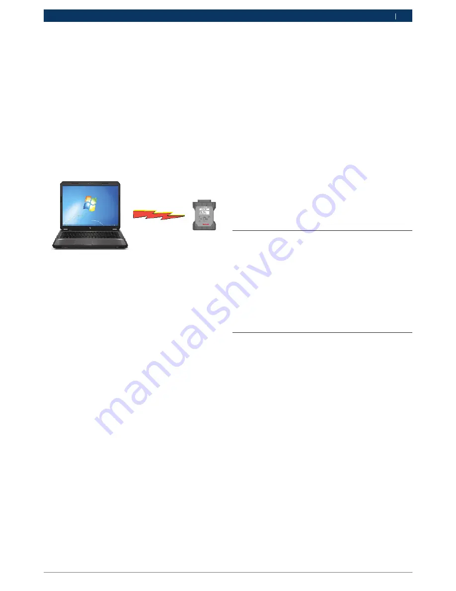
The following illustration shows a single VCI connected 
to a laptop PC using Point-to-Point Wireless communi-
cation.

Use the following procedure to configure your VCI for 
Point-to-Point Wireless communication. Note that the 
steps presented below assume you are running the Win-
dows 7 ,8 or 10 operating system on your PC. The steps 
for other versions of the Windows operating system 
may be slightly different.

1. 

Insert the Wireless USB adapter in an available USB 
port on your PC. Power-on your PC.

2. 

Wait for the USB driver to be automatically configu-
red during the first time the USB dongle is inserted 
in the PC USB Port. 
 
Power up the VCI by connecting the VCI to the 
vehicle DLC. 
 
Note, powering the VCI using the USB cable only 
does not supply enough voltage to run the WiFi 
Dongle. 
 
Allow the VCI to boot completely

3. 

Start the VCI Manager software by double-clicking 
the icon on the PC desktop.

4. 

The VCI Icon in the VCI Explorer tab should now 
have green bars displayed on top of the VCI Icon 
(see chart in section 8.4 for an example of what 
the green bars look like as well as other icons that 
could be displayed). 
 

The green bars indicate that PC sees the VCI in 
wireless mode. You can also move your mouse 
over the VCI Icon icon in the VCI Explorer tab and 
bubble help will display how the VCI is connected 
to the PC.

5. 

Select the VCI with Green bars in the VCI Manager 
Explorer tab and click the <connect> button.  -> 
Once connected, a green check mark will replace 
the green bars. The green check mark confirms the 
VCI is communicating P-to-P with the PC.  Once 
connected, select the Disconnect button and close 
the VCI Manager application.

5.3.3 

Set Factory Default Settings

Selecting the Set Factory Default button on Network 
Setup tab reconfigures your VCI to the Point-to-Point 
communications settings it had when it left the factory. 
Any software upgrades that have been installed to the 
VCI are still installed.

5.4 

Power On Self-Test (POST)

When you first apply power to the VCI, the Power On 
Self-Test (POST) runs. You should observe activity on 
the LCD display and hear the audible “BEEP’ indicating 
that the VCI is working properly.

When the start-up phase is finished the green Power 
LED is permanently on and the four status indicator 
symbols are shown along the bottom edge of the LCD 
display.

5.5 

Connecting the VCI to a Vehicle

The MTS 6513 Vehicle Communication Interface kit con-
tains the J1962 16/26 pin Data Link Connector (DLC) 
cable to connect the VCI to the vehicle.
Refer to the electrical wiring diagram for the vehicle you 
are testing to determine the location and type of Data 
Link Connector (DLC) installed on the vehicle. 

1. 

Connect the 15-pin end of the DLC cable to the top 
of the VCI, then tighten the screws.

2. 

Connect the 16-pin end of the DLC cable to the 
vehicle DLC connector.

Powering the VCI

The VCI can be powered by the vehicle’s 12-volt battery 
or by the USB cable connected to your PC.

To use the Vehicle Battery, connect the VCI directly to 
the vehicle using the DLC cable.

To use USB power, connect the VCI to your PC using 
the USB cable.

Summary of Contents for 1699200115

Page 1: ... 7 4 11 1 Serial Data Interfaces 7 4 11 2 Non Serial Data Interfaces 7 5 Getting Started 7 5 1 Installing the VCI Manager Software 8 5 2 Setting Up the VCI Hardware 8 5 2 1 Identifying Your VCI 8 5 2 2 Updating the VCI Software 8 5 2 3 Configuring the VCI Using VCI Manager 8 5 2 4 Check PC and VCI Software Versions 9 5 3 Setting Up Wireless Communications 9 5 3 1 Enabling Access Point Wireless Com...

Page 2: ...e at the time of publication However the right is reserved to make changes at any time without notice Before starting up connecting and operating Bosch products it is absolutely essential that the operating instructions user manual and in particular the safety instructions are studied carefully By doing so you can eradicate any uncertainties in handling Bosch products and thus associated safety ri...

Page 3: ...health are prevented by properly disposing of the MTS 6513 3 3 FCC Compliance This equipment has been tested and found to comply with the limits for a Class A digital device pursuant to Part 15 of the FCC rules These limits are designed to provide reasonable protection against harmful interfe rence when the equipment is operated in a commercial environment This equipment generates uses and can rad...

Page 4: ...meters right angle F 00K 108 988 Velcro Cable Tie Wrap 3 4 x 5 1699200050 Using the VCI Manager PC application software you configure the MTS 6513 to communicate with a host computer The MTS 6513 is capable of communicating over a USB cable or wireless WLAN The MTS 6513 has a LCD display which can be used to run applications in stand alone mode without a PC 4 2 User group The product may be used b...

Page 5: ... runs on the Microsoft Windows operating system to configure and update VCIs The VCI Manager software allows the configuration of VCI to host PC communications and facilitates VCI firmware updates 4 9 J2534 Pass Thru Support The MTS 6513 works with an OEM supplied J2534 PC computer applications PC program for ECU Reflashing and diagnostic applications The MTS 6513 supports pass thru programming of...

Page 6: ...up arrow and down arrow keys to adjust Contrast and Backlight R R Press the left arrow key to save your settings and go back to the previous screen Configure the SuperCap Function R R Depress the Home Enter F2 keys simultaneously to reach the Main Menu screen R R Select the SuperCap sub menu using the up arrow down arrow keys R R Use the right arrow key to navigate to the SuperCap sub menu R R In ...

Page 7: ...USB cable to configure your VCI using VCI Manager 5 2 1 Identifying Your VCI The VCI label is located on the back of the VCI The VCI identification number has two parts a manufacturing code for traceability and a unique serial number The serial number is used to identify the VCI in the VCI Manager software You will need to refer to this serial number when you are using VCI Manager to configure the...

Page 8: ...ersion match you can use your VCI with this PC 5 3 Setting Up Wireless Communications The MTS 6513 VCI is capable of communicating on your workshop network over USB and Wireless The Net work Setup tab in the VCI Manager software provides a number of functions used to select and configure the VCI network connection interfaces including wireless access and security settings If you have purchased a W...

Page 9: ...k mark will replace the green bars The green check mark confirms the VCI is communicating P to P with the PC Once connected select the Disconnect button and close the VCI Manager application 6 Select the Network Setup tab 7 Select the Wireless tab 8 Select the Enable Wireless Interface check box in the Interface Control section Once you enable the interface the IP Address Configuration box and the...

Page 10: ...on icon in the VCI Explorer tab and bubble help will display how the VCI is connected to the PC 5 Select the VCI with Green bars in the VCI Manager Explorer tab and click the connect button Once connected a green check mark will replace the green bars The green check mark confirms the VCI is communicating P to P with the PC Once connected select the Disconnect button and close the VCI Manager appl...

Page 11: ...l allows you to select multiple connection methods R R Device on USB R R Default Device R R Device Explorer If the box to the left of the method is checked then the connection method is attempted when connecting If the box is not checked then the connection method is skipped The connection methods are attempted sequentially from top to bottom To change the order select a connection method and clic...

Page 12: ...ts first using USB if available if USB is not available the VCI connects using wireless Recommendations R R Check that the cables are securely attached to the VCI the VCI has completed its power up sequence the connector pins are clean and the VCI Manager software is running R R If connecting using USB check that the VCI USB con nection is detected by Windows Connect the VCI to the PC USB port the...

Page 13: ...the Recovery Procedure Error reprogramming the VCI Go to Recovery Mode There was a problem reprogramming the VCI Recovery Procedure Use the following procedure to recovery the software on the VCI 1 Remove power from the VCI Ensure that all the LEDs are off 2 Remove end cap Press and hold the Recovery But ton down while you apply power to the VCI using the USB cable You will see the word Fail Safe ...

Page 14: ...INTERFACE USB UNIVERSAL SERIAL BUS A COMMON STANDARD FOR INTERFACING WITH A PC VCI VEHICLE COMMUNICATION INTERFACE VCI MANAGER PC SOFTWARE THAT CONFIGURES TESTS AND UPDATES THE VCI VDC VOLTS DC WLAN WIRELESS LOCAL AREA NETWORK 11 Hardware Specifications The following table lists the various hardware characte ristics of the MTS 6513 MTS 6513 HARDWRE SPECIFICATIONS HOST INTERFACE Wired High Speed 48...

Reviews: