12
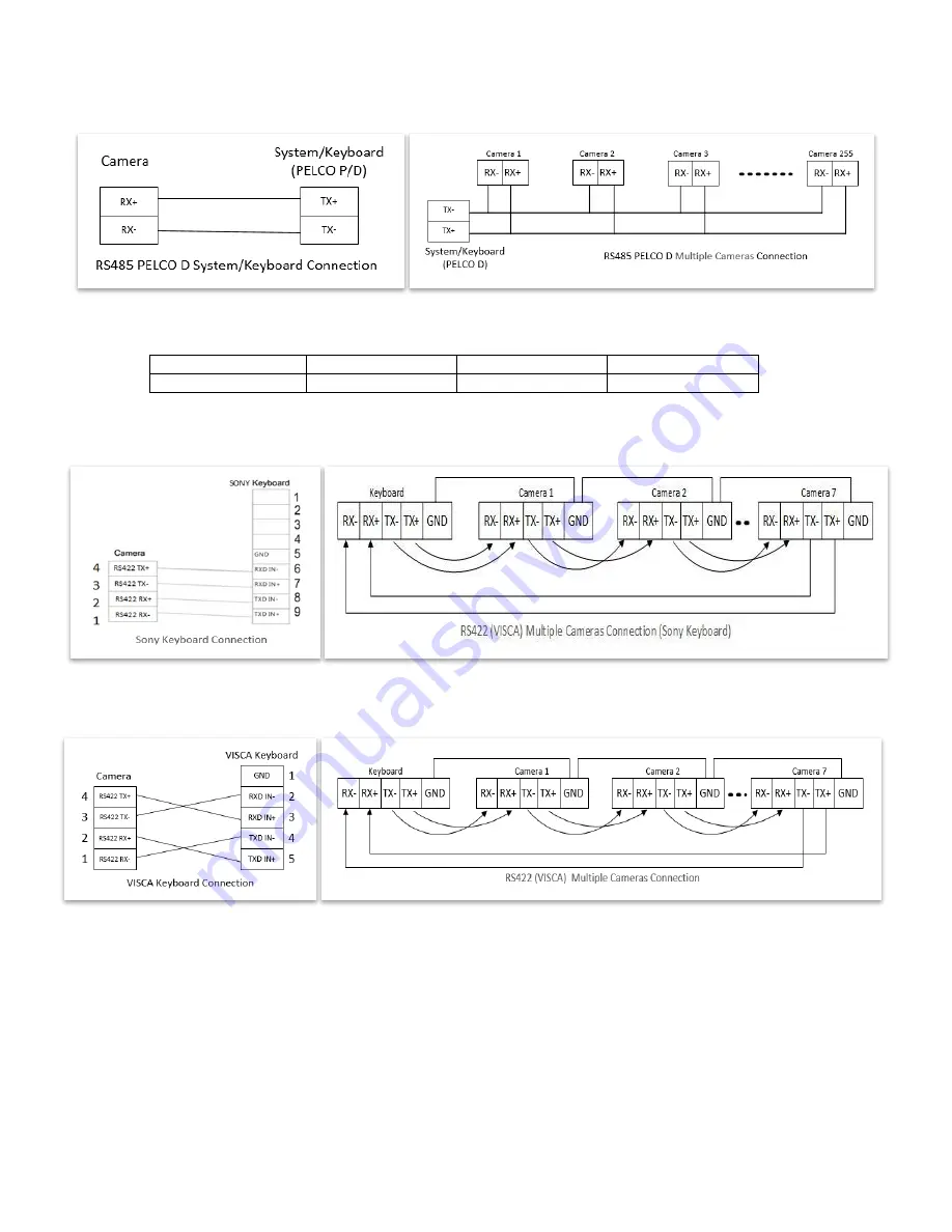
1.1 RS485 (PELCO D) control connection diagram
Connect the Camera’s RS485+ and RS485 to RS485/TX+ and RS485/TX- on the control system/keyboard. The
identity of the control system or equipment may be different; the corresponding relationship is as follows:
RS-485 A
RX+
RS-485 D+
RS-485 +
RS-485 B
RX-
RS-485 D-
RS-485 -
1.2 RS422 (VISCA) control connection diagram
SONY Keyboard RS422 Connection
VISCA (None-Sony) Keyboard RS422 Connection
Setup Camera ID, Baud Rate and Control Protocol
In order for you to control a camera, the camera ID, baud rate and control protocol have to be set up in advance,
Baud rate and the camera ID setting on the camera have to be the same as baud rate and camera ID setting on the
system/control keyboard. The camera can auto detect the VISCA and PELCO-D, only need to set up the camera
address and baud rate.
Connect the camera to a monitor. There is an initial setting page displaying on the screen for 5 seconds when the
camera is powered on. On the page, it shows the factory default setting of the camera ID, baud rate and other
information. Suggest taking a picture of this default setting information for setting keyboard use. Set the keyboard
or control system to match the camera ID, baud rate setting with the camera.
1.
Camera supports VISCA and PELCO-D protocols, protocol is detected automatically by the camera.
2.
Factory Default Setting: For both SDI and IP video, Baud Rate: 9600, Camera ID: 001, Pelco Protocol.
Summary of Contents for SD5SN-M-10162017
Page 6: ...6 WHAT S IN THE BOX Accessories Optional ...
Page 24: ...24 Dimensions Unit mm ...
Page 25: ...25 Specifications ...
Page 26: ...26 ...
Page 27: ...27 www bolintechnology com 2082 TECHNOLOGY LLC dba BOLIN TECHNOLOGY ...


