background image


11. REPLACING THE SENSOR 

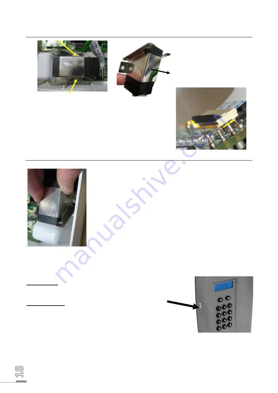
11.1  Dismantling the biometric sensor 

On  the  interior  of  the  terminal 

front  panel,  remove  the  two 

screws  holding  the  biometric 

sensor in place. Then remove the 

sensor  and  take  off  its  metallic 

fixing  support,  sliding  it  in  the 

direction of the arrow. 


On the terminal’s electronic board, lift the black connector 

locking  tab  as  shown  opposite.  Then  free  the  connector 

ribbon. 


11.2  Re-assembling the biometric sensor 


Connect  the  new  sensor  by  sliding  the  ribbon  into  the 

connector,  with  the  plastic  insulating  part  on  the  board  side, 

then fold back the black locking tab. 

Insert the sensor into its metallic support and hold it as shown 

opposite.  Put  back  the  two  retaining  screws  using  a  Philips 

screwdriver. 


12. USING BARCODE SCANNERS 

The P

RIO

 terminals that are compatible with the activity clocking operations have a label. 


Wired reader 

Connect the reader to the USB port on the activity P

RIO

.


Wireless reader 

Connect  the  reader  support  to  the  USB  port  on  the  activity 

P

RIO

Follow the start-up instructions for the wireless reader provided 

with it. 


Summary of Contents for KELIO PRIO V2

Page 1: ...ximity MIFARE Classic and Desfire CSN badge reader no USB key function possible 926159 Proximity MIFARE Desfire Bodet Number badge reader no USB key function possible 926164 Proximity MIFARE Desfire Bodet Number badge reader no USB key function possible 926274 Biometric fingerprint standalone reader 926186 Biometric fingerprint standalone reader 926275 Biometric fingerprint proximity STID reader 9...

Page 2: ...S TO TAKE IN RELATION TO BIOMETRIC IDENTIFICATION PROCESSES 16 10 MESSAGES ON THE TERMINAL 17 11 REPLACING THE SENSOR 18 11 1 DISMANTLING THE BIOMETRIC SENSOR 18 11 2 RE ASSEMBLING THE BIOMETRIC SENSOR 18 12 USING BARCODE SCANNERS 18 13 SAFETY INSTRUCTIONS AND EQUIPMENT PROTECTION 19 14 TECHNICAL CHARACTERISTICS 20 1 INITIAL CHECK In its original packaging each terminal is delivered with A bag con...

Page 3: ...ng a USB flash drive The USB flash drive is not supplied with the terminal It is possible that some flash drives on the market may not be compatible with the terminal Check that the terminal is operational using other USB flash drives if the USB flash drive does not work The following USB flash drives have been tested on the product this list is not exhaustive DANE ELEC CAP LESS 2Gb DANE ELEC CUBE...

Page 4: ...ith low temperature variations and far from any electromagnetic interference sources contactors motors other badge swipe readers etc Partially unfasten the lower screw A from the terminal and take the holding plate off the terminal Fix the holding plate on the wall using the 3 screws and rawlplugs 115mm 80mm 15mm A ...

Page 5: ...erminal on the two upper pins of the holding plate Tilt the bottom of the terminal towards the holding plate to close it and make sure that the wires still remain in the passage on the bottom of the terminal casing Tighten the lower screw A of the holding plate in order to fix the terminal Remove the protection sheet from the front Connect the power supply cable to a mains socket The terminal is r...

Page 6: ...roduct is powered using the POE option With POE option KELIO PRIO is powered only by the Ethernet cable terminal block C There is therefore no terminal block A present on the KELIO PRIO terminal Voltage supplied by the POE switch for the terminal if using the POE option IEEE 802 3af 12 95W category 3 Connect the bell relay if necessary To do this connect the contacts for terminal block B of the re...

Page 7: ...ery fully loosen screw A and remove the back piece as shown on the diagram opposite Push the clamping collar provided with the battery B into the two holes D provided for the purpose Position the battery B in its housing C positioning it as far to the left as possible along the left hand wall at the back of the terminal Tighten the collar as firmly as possible to hold the battery B in its housing ...

Page 8: ... left of the lithium battery respecting the polarisation using the connector s guide Close the unit taking care not to jam the cable E between the back and the front of the terminal Replace the lower closing screw A to secure the back to the front of the terminal E F A ...

Page 9: ...wired mode described hereafter the terminal will be set in the language of the software Welcome screen Main menu Date and time setup p 10 Return to the upper level Time drifting setup p 10 Boot and Ping of the terminal p 10 IP address subnet mask and gateway setup of the terminal p 10 Clearing the terminal data Total clearing purge of the terminal factory settings Playback of 5 melodies in series ...

Page 10: ... Wait until the end of the synchronisation process and remove the key from the terminal when being asked for it 4 Plug the USB drive into the Kelio server then access the application s HR User module 5 Go to the menu TOOLS USB TERMINAL CLOCKING RETRIEVAL 6 3 Manually setting the time of the terminal To set the terminal time press F2 enter the main menu with the administrator code set up in the Kel...

Page 11: ...P to configure the terminal s IP address press 2 MASK to configure the terminal s network mask address and press 3 GW to fill in the terminal s gateway address if used By default at production output the terminal is configured with the following addresses IP address 192 168 1 233 Network mask 255 255 255 0 Gateway 0 0 0 0 7 1 IP address configuration Press 1 IP from the IP configuration menu and e...

Page 12: ...he remote machine The terminal displays the following message during the ping test The terminal displays the following result if the remote machine responds to the ping If the remote machine does not respond to the ping the terminal displays the following result 8 ADJUSTING THE DISPLAY CONTRAST The LCD s screen contrast can be adjusted The contrast adjustment is activated for a maximum of 3 second...

Page 13: ...n or out When the clocking is successful the time and the employee s badge number are displayed on the terminal 9 1 2 Registering the employees using a badge number Employees who cannot be enrolled or whose fingerprint quality is not high enough can clock in without biometric identification by entering a badge number on the terminal s keypad A badge number must have been authorised previously in t...

Page 14: ...2 to delete the data by choosing the badge number from a list Scroll through the list with keys 1 and 2 Press E to confirm 9 2 In Ethernet mode Before you can clock using the biometric sensor you must enrol yourself To do so enter the numerical code using the biometric terminal keypad configured in the Kelio software installer Hardware Terminals SITES MAINTENANCE menu by default 1234 then press E ...

Page 15: ...g keys 1 and 2 in this case Depending on the reader s technology or the clocking mode which is configured certain menus will not be available and the following screen is displayed without prior selection Caution key 3 lets you delete all enrolments 4 Swipe the badge in front of the reader when the terminal displays this message 5 The start of the employee s first name surname is displayed Press E ...

Page 16: ...u enrol the index fingers Enrolment may be difficult if the fingers are thin In this case you must start again until you achieve sufficient quality Ambient brightness The brightness may cause the reading quality to vary The reader must not be placed under any direct light source that may alter reading Clean fingers The finger to be read must be clean and not be excessively dry Clean reader Check t...

Page 17: ...your time when you enrol To guarantee the optimum level of recognition the score obtained during enrolment must be greater than 90 If you want to restart an enrolment you must delete the enrolment of the employee and restart the entire procedure All the precautions to be taken when you use biometrics are specified in a document that was provided when you bought the system 10 MESSAGES ON THE TERMIN...

Page 18: ...sor Connect the new sensor by sliding the ribbon into the connector with the plastic insulating part on the board side then fold back the black locking tab Insert the sensor into its metallic support and hold it as shown opposite Put back the two retaining screws using a Philips screwdriver 12 USING BARCODE SCANNERS The PRIO terminals that are compatible with the activity clocking operations have ...

Page 19: ... maintenance on the terminal before detaching the holding plate and the casing from the terminal unplug the power supply block and shut off the mains supply circuit breaker disconnecting switch for any relay switched dangerous voltage Apart from the relay connection all devices or circuits connected to the terminal MUST be of SELV type separated extra low voltage The use of clamping collars on the...

Page 20: ...here is a risk of explosion if the lithium battery is inserted incorrectly Use the same model or an equivalent model recommended by this manual when changing the battery Follow the instructions in this manual when replacing the lithium battery The battery must only be replaced by maintenance staff The battery must be a CR1225 type Lithium battery Relay switch Disconnection 230VAC 50Hz 60Hz 1A maxi...

Reviews: