background image

3

Clearview 4:2 12

Quick Guide

Step 2: Connecting to a PC/Laptop

ETHERNET ACCESS:

Local or remote communication with the unit is only possible through a GUI-based menu via web browser (Chrome or Firefox 

is recommended)

. Before you can communicate with the unit, you must configure your computer's IP address to be in the 

same subnet as the units default IP address. To do so, follow these steps:

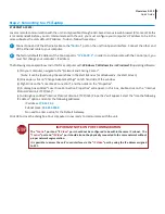
Connect one end of the Ethernet cable to the “

Control

” port on the unit front-panel interface. Connect the other end 

of the Ethernet cable to your computer.

The factory default IP address of the Control port is “

172.16.70.1

”. In order to communicate with the Control port, you 

must first change your computer's IP address.

1

2

The following steps explain how to do this for a computer with  

Windows 7Windows 8.x or Windows 10

 operating software: 

(a) On your computer, navigate to the “Network and Sharing Center”.
     

 (Note: It can be found using the search box in the Start Menu or for Windows 8.x, the Start Screen)

(b) Once open, click on “Change Adapter Settings” on left hand side of the window.
(c) Right-click on the “Local Area Connection”, and then click on the “Properties”.
(d) A dialog box entitled “Local Area Connection Properties” will appear. In this box, double-click on the “Internet 

Protocol Version 4 (TCP/IPv4)”.

(e) A dialog box entitled “Internet Protocol Version 4 (TCP/IPv4) Properties” will appear. Select the “Use the following 

IP address” option and enter the following addresses:

IP address: 

172.16.70.2

Subnet mask: 

255.255.255.0

No need to enter a value for the Default Gateway.

Click OK to close the dialog box. Your computer is now ready to communicate with the unit.

IMPORTANT NOTE ON PORT CONFIGURATION

The “

Control

” port and “

IP Video”

 port should not be configured to be within the same IP subnet.  The 

Control

” port and “

IP Video

” port should also not be physically connected to the same network without 

proper network segmentation.

It is possible to access the unit's user interface via the “

IP Video

” port by using the IP address assigned 

to XC1.

Summary of Contents for Clearview 4:2 12

Page 1: ...hannels H 264 to MPEG 2 HD Transcoder for up to 12 SPTS Channels Clearview 4 2 12 Quick Guide Blonder Tongue Labs Inc ISO 9001 2015 Certified P N 651245400A Rev 070921 All Rights Reserved Specifications subject to change without notice All trademarks are property of their respective owners ...

Page 2: ...front panel Temperature LED IMPORTANT NOTE BEFORE YOU BEGIN The Key2License from Technicolor is required and MUST be installed on the COM3000 2000 unit prior to setup of this unit See Section 3 of the User Manual for more information The Clearview 4 2 is designed to be installed in a standard 19 inch 483 mm rack EIA 310 D IEC 60297 and DIN 41494 SC48D To install secure the unit s front panel to th...

Page 3: ...be found using the search box in the Start Menu or for Windows 8 x the Start Screen b Once open click on Change Adapter Settings on left hand side of the window c Right click on the Local Area Connection and then click on the Properties d A dialog box entitled Local Area Connection Properties will appear In this box double click on the Internet Protocol Version 4 TCP IPv4 e A dialog box entitled I...

Page 4: ...ab located on the right side of the navigation menu at the top Step 4 Basic Configuration System Status Once you are logged into the unit you will be presented with the System Status page Status tab Status Page Full View Step 3 Login to the Controller An Ethernet Cable should be connected between your PC and the Control port on the unit Open a Web browser Chrome or Firefox recommended and type htt...

Page 5: ...tem tab to change the System Settings including unit identification and network settings System Page Full View The following Ethernet Settings can be changed IP address Subnet Mask Default Gateway and the Primary and Secondary DNS In addition the network settings for each transcoder slave are individually configurable Click Apply Settings in order to save new or changed settings This section allow...

Page 6: ...t is located in the Transcoders Settings tab Transcoders Settings Page Example Transcoders Status The information shown on this screen indicates the status of each transcoder A visual status of the pipeline is also shown on the left side When hovering over a Transcode block the corresponding status table highlights Transcoders Status Page Visual and Informational Status Pipeline Status States Ligh...

Page 7: ... 0 3 The Management PC is configured to be at 192 168 3 5 with a subnet mask of 255 255 0 0 Note The subnet mask of the Video Source Sink device must be configured to be on the same subnet mask as the Management PC Accessing devices from the Management PC To access the Video Source Sink device go to http 192 168 3 18 To access the Clearview 4 2 12 unit go to http 192 168 6 71 Note Additional Clear...

Page 8: ...entation Updates Download the latest User Manual PDF by visiting our website Navigate to the product page by entering the full Model Name or Stock Number in the search field Upon reaching the product page the User Manual download link will be located beneath the product image Firmware Updates are available under Tech Support in the Resources section of the website General instructions for the FTP ...

Reviews: