


06
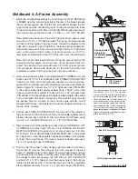
Moldboard & A-frame Assembly (Continued)
6.
Begin the draw latch installation by first removing the DRAW LATCH
MOUNT PIN, SPACER & COTTER PIN from the assembly. By removing
this pin, the INNER DRAW LATCH PLATES can swing free. Proceed
to remove the INNER DRAW LATCH PLATE LIFT CYLINDER MOUNT
PIN. Position the plates on either side of the lift cylinder rod and insert
the pin through the plates and cylinder rod. With the cylinder con-
nected to the inner draw latch plates, rotate the draw latch assembly
toward the draw latch mount holes on the A-frame. Align the holes in
the outer draw latch plate with those of the inner draw latch plates
and the A-frame. Note: The A-FRAME LATCH, located at the rear
center of the A-frame, should be raised up to insert the draw latch
mount pin. Pull the A-FRAME LATCH PULL PIN out and rotate the
latch counterclockwise if it is locked into position. Secure the assembly
to the A-frame by replacing the draw latch mount pin spacer and cotter
pin. Reset the A-frame latch so the latch pull pin locks into place.
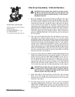
Once you have completed the draw latch installation, proceed to assemble
the manifold. The manifold, pump and coil harness have been joined
together at the factory; however, the manifold contains several components
that you will need to install prior to securing the assembly to the A-frame.
7.
Each of the 4 HOSE PORTS on the HYDRAULIC MANIFOLD are
covered with stretch wrap. Remove the wrap and install the appropriate
fitting (illustrated on page 7) in its respective port.
Note: All ports are identified by a stamped number on the manifold.
The numbers also identify the hydraulic functions, which can be ref-
erenced on the label under the hydraulic pump and manifold cover
(see illustration on page 7).
Outer Draw
Latch Plate
Draw Latch
Mount Pin
(1" DIA. x 3-1/4")
Hydraulic
Lift / Lower
Cylinder
Draw Pin
(1" DIA. x 4-1/2")
Clevis Pin
(3/4" x 3-7/16")
Hex Head Cap Screw
(3/4"-10 x 3-1/2")
Cotter Pin
(3/16" x 2-1/2")
Inner Draw Latch Plate
Lift Cylinder Mount Pin
(5/8" DIA. x 2-1/16")
Draw Latch Arm
Pivot Pin
(3/4" DIA. x 2-1/16")
Cotter Pin
(1/4" x 1-1/2")
Top Lock Nut
(3/4"-10)
Inner Draw
Latch Plate
Draw Latch
Arm Weldment
Draw Latch
Finger Weldment
A-Frame Latch
Lock Pin
Draw
Pin
A-Frame Latch
Rotates Clockwise
And Hooks Onto
Draw Pin
A-Frame
Latch
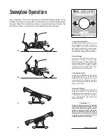
To mount the straight blade, the A-frame latch
should be lowered over the draw pin– this allows
the draw latch to pull the plow into the undercar-
riage. Once the plow is safely attached to the
undercarriage, rotate the A-frame latch counter-
clockwise until the lock pin snaps into place. The
A-frame latch is only used to mount the plow.
The A-frame latch should always be locked in
place when not in use.
Printed
Label
All of the hoses shipped with the snowplow con-
tain a printed label (with a part number) applied
to the hose. Install the following hoses to their
respective ports on the manifold:
Hose P/N 60294
Port #1
Hose P/N 60296
Port #2
Hose P/N 60293
Port #3
Hose P/N 60295
Port #4
Draw Latch Assembly
The draw latch consists of a series of intercon-
nected plates and pins that attach to the A-frame
and the hydraulic lift cylinder.
Summary of Contents for 680LT
Page 17: ...Notes 15 Notes...