


1. Make sure the tubing and threads are clean.
2. Lubricate the threads with 10W hydraulic oil.
3. Hand tighten the nut/sleeve to appox. 30 in-lbs.
4. Make alignment marks on the nut and fitting.
5. Proceed to tighten to turns or ft-lb values.
6. When fully tightened make a 2nd set of align-
ment marks at the fully tightened position.
Note: Torque values specified are for threads
lubricated with 10W hydraulic oil.
Sizes -02 through -08 are less tolerant to over-
torque abuse. This will reduce the clamping force
resulting in loss of seal and reduction in flow.
37˚ JIC Flare Torque Values
Turns
Size
ft-lbs min./max.
Assembly Steps w/Visual Check
N/A
-02
6 - 7
N/A
-03
8 - 9
2
-04
11 - 12
2
-05
14 - 15
1-1/2
-06
18 - 20
1-1/2
-08
36 - 39
1-1/2
-10
57 - 63
1-1/4
-12
79 - 88
1
-14
94 - 103
1
-16
108 - 113
1
-20
127 - 133
1
-24
158 - 167
1
-32
245 - 258
Metric Class 8.8
Metric Class 10.9
Tightening Torque
Tightening Torque
“Lubricated”
“Dry”
“Lubricated”
“Dry”
5
1,389
3.42 ft-lbs
4.56 ft-lbs
5
1,987
4.89 ft-lbs
6.52 ft-lbs
6
1,965
5.81 ft-lbs
7.80 ft-lbs
6
2,812
8.34 ft-lbs
11.07 ft-lbs
7
2,826
9.74 ft-lbs
12.99 ft-lbs
7
4,044
13.95 ft-lbs
18.60 ft-lbs
8
3,579
14.10 ft-lbs
18.82 ft-lbs
8
5,121
20.15 ft-lbs
26.94 ft-lbs
10
5,672
27.90 ft-lbs
37.27 ft-lbs
10
8,116
39.92 ft-lbs
53.28 ft-lbs
12
8,243
48.71 ft-lbs
64.94 ft-lbs
12
11,796
69.74 ft-lbs
92.25 ft-lbs
14
11,246
77.49 ft-lbs
103.32 ft-lbs
14
16,092
110.70 ft-lbs
147.60 ft-lbs
16
15,882
125.46 ft-lbs
166.79 ft-lbs
16
21,970
173.43 ft-lbs
231.00 ft-lbs
18
19,423
171.95 ft-lbs
229.52 ft-lbs
18
26,868
238.37 ft-lbs
317.34 ft-lbs
20
24,784
243.54 ft-lbs
325.46 ft-lbs
20
34,284
338.00 ft-lbs
450.18 ft-lbs
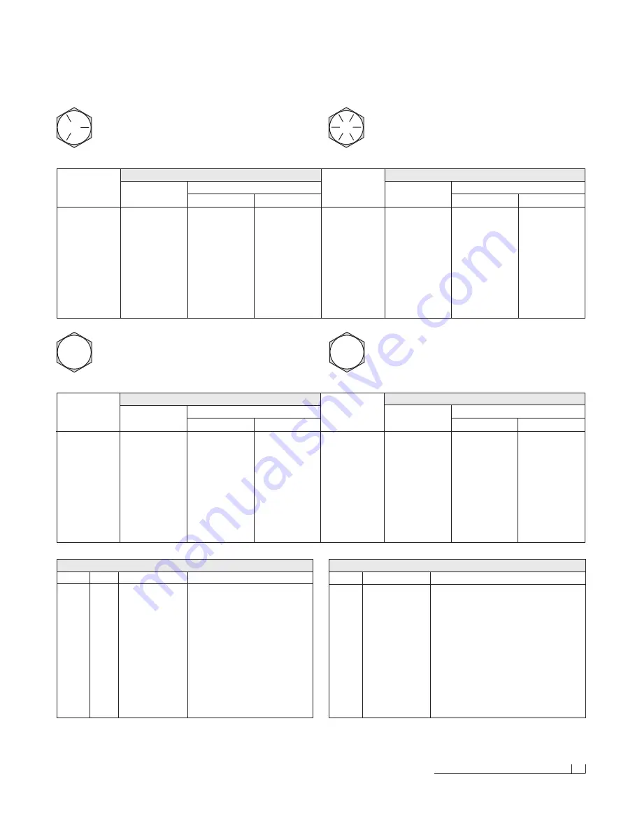
Torque Specifications
33
Torque Specifications
SAE J429 - Grade 5
SAE J429 - Grade 8
Tightening Torque
Tightening Torque
“Lubricated”
“Dry”
“Lubricated”
“Dry”
1/4-20
2,000
6.25 ft-lbs
8.34 ft-lbs
1/4-20
2,850
8.92 ft-lbs
11.93 ft-lbs
5/16-18
3,350
13.25 ft-lbs
17.5 ft-lbs
5/16-18
4,700
18.35 ft-lbs
25.44 ft-lbs
3/8-16
4,950
23 ft-lbs
31 ft-lbs
3/8-16
6,950
32.5 ft-lbs
44 ft-lbs
7/16-14
6,800
37 ft-lbs
50 ft-lbs
7/16-14
9,600
53 ft-lbs
70 ft-lbs
1/2-13
9,050
57 ft-lbs
75 ft-lbs
1/2-13
12,800
80 ft-lbs
107 ft-lbs
9/16-12
11,600
82 ft-lbs
109 ft-lbs
9/16-12
16,400
115 ft-lbs
154 ft-lbs
5/8-11
14,500
113 ft-lbs
151 ft-lbs
5/8-11
20,300
159 ft-lbs
211 ft-lbs
3/4-10
21,300
200 ft-lbs
266 ft-lbs
3/4-10
30,100
282 ft-lbs
376 ft-lbs
7/8-9
29,435
321 ft-lbs
430 ft-lbs
7/8-9
41,550
454 ft-lbs
606 ft-lbs
1-8
38,600
482.5 ft-lbs
640 ft-lbs
1-8
54,540
680 ft-lbs
900 ft-lbs
Clamp Loads
(Pounds)
Clamp Loads
(Pounds)
Nominal
Thread
Size
Nominal
Thread
Size
Grade Identification Marking for J429 - Grade 5 Bolt
• Material: Medium carbon steel: quenched and tempered
• Minimum Proof Strength: 85,000 psi
• Minimum Tensile Strength: 120,000 psi
• Core Hardness Rockwell (min.): C25, (max.): C34
• Minimum Yield Strength: 92,000 psi
Grade Identification Marking for J429 - Grade 8 Bolt
• Material: Medium carbon alloy steel:quenched and tempered
• Minimum Proof Strength: 120,000 psi
• Minimum Tensile Strength: 150,000 psi
• Core Hardness Rockwell (min.): C33, (max.): C39
• Minimum Yield Strength: 130,000 psi
8.8
Clamp Loads
(Pounds)
Clamp Loads
(Pounds)
Diameter
(millimeters)
Diameter
(millimeters)
Grade Identification Marking for Metric - Grade 8.8 Bolt
• Material: Medium carbon steel: quenched and tempered
• Minimum Proof Strength: 580 MPa
• Minimum Tensile Strength: 800 MPa
• Core Hardness Rockwell (min.): C22, (max.): C32
• Minimum Yield Strength: 640 MPa
10.9
Grade Identification Marking for Metric - Grade 10.9 Bolt
• Material: Low carbon alloy steel: quenched and tempered
• Minimum Proof Strength: 830 MPa
• Minimum Tensile Strength: 1040 MPa
• Core Hardness Rockwell (min.): C32, (max.): C39
• Minimum Yield Strength: 940 MPa
O-Ring Boss Torque Values
Size
ft-lbs min./max.
O-Ring Boss Assembly
-02
6 - 7
-03
8 - 10
-04
13 - 15
-05
17 - 21
-06
22 - 25
-08
40 - 43
-10
43 - 57
-12
68 - 75
-14
90 - 99
-16
112 - 123
-20
146 - 200
-24
154 - 215
-32
218 - 290
1. Verify the port, O-ring, sealing surfaces, and threads are
clean and free of damage.
2. Lubricate the threads and the O-ring with 10W hydraulic oil.
3. For an adjustable O.R.B., completely back-off the lock nut
and the washer.
4. Hand tighten the fitting until it contacts the port spotface.
Point the elbow or tee in the desired direction and hold.
5. Proceed to tighten to the proper specified torque value.
Note: Torque values specified are for threads lubricated
with 10W hydraulic oil.
Disclaimer: All torque values included in the charts above are advisory only, and their use by anyone is entirely voluntary. Reliance on the contents for any purpose by anyone is the sole risk of that person and Blizzard Corporation is not responsible for any loss, claim or damages
arising therefrom. Blizzard Corporation has made an effort to present the above contents accurately, but we do not guarantee its completeness or validity. This information is subject to change at any time, without notice. Blizzard Corporation makes no representations or warranties,
express or implied, in connection with the information.
Summary of Contents for 680LT
Page 17: ...Notes 15 Notes...