


10
Electrical Assembly - Vehicle Harness
Electrical Assembly - Vehicle Harness
CAUTION: Always perform the vehicle wire harness assem-
bly with the vehicle off and the keys out of the ignition. Use
caution when testing the electrical wires for the vehicle’s
headlight functions.
1.
Begin the installation of the electrical harness under the hood. Insert
the WHITE POWER CONNECTOR & RED POWER WIRE (with FUSE)
end of the harness through the driver’s side fire wall access panel into
the vehicle cab. Note:You may need to widen an opening or cut access
to the cab interior to facilitate the assembly. Loosely position the
remaining portion of the harness over the driver’s side fender well and
place the MOLDED RUBBER POWER CONNECTOR near the bumper.
Note: Keep the plow and vehicle rubber power connector pins lubri-
cated with a liberal amount of dielectric grease. Always replace the
protective RUBBER WEATHER CAPS when the plow is disconnected
from the vehicle.
2.
Next, attach the POWER CONTACTOR (SOLENOID) to the driver’s
side wheel well or engine fan guard using two 12-14 x 3/4" hex washer
self-drilling screws. Note: Some model vehicles provide mounting
locations for accessory components. Always mount the solenoid with
the terminals facing up. This will extend the useful life of the solenoid.
Connect the 24" BLACK GROUND WIRE to either small terminal on
the solenoid and attach the opposite end to the vehicle with one hex
washer self-drilling screw. Locate the BROWN/WHITE PUMP SOLE-
NOID ACTIVATION WIRE on the wire harness and position the eyelet
over the remaining small terminal on the contactor. Secure it with the
hardware provided on the solenoid.
3.
Proceed to connect the BLACK VEHICLE WIRE HARNESS GROUND
WIRE to the negative terminal on the vehicle’s battery. Cut the wire to
length and crimp a 3/8" DIA. END RING TERMINAL on the wire. It is
also recommended that the ring terminal be soldered. Note: The har-
ness should be secured to the vehicle prior to taking the necessary
measurement. Measure the distance needed for the RED POWER
WIRE to reach the solenoid and properly secure an end ring terminal
to it. Connect the power wire to either large terminal on the solenoid.
CAUTION: Do not fasten the wire harness to areas that come
in contact with moving engine parts or possess extreme
heat.The harness could become tangled and/or melt causing
electrical failure and vehicle damage.
4.
Attach and solder an end ring terminal to both ends of the remaining
length of the red 4 gauge wire. Connect one end of the wire to the
open terminal on the solenoid and the remaining end to the positive
terminal on the battery.
5.
With the vehicle harness secured to the truck, position the MAIN
LIGHTING HARNESS such that both of the large, gray VEHICLE
HEADLIGHT CONNECTORS are near the truck headlights and the
smaller, black PLOW HEADLIGHT CONNECTORS are near the grill
of the vehicle.
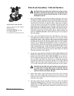
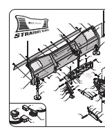
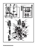
A
B
C
D
Heavy-Duty Power Contactor (Solenoid)
There are four wires that need to be attached to
the power contactor:
(A) Red Power Battery Wire
(B) Vehicle Wire Harness Red Power Wire
(C) 24" Black Ground Wire
(D) Brown/White Pump Solenoid Activation Wire
Summary of Contents for 680LT
Page 17: ...Notes 15 Notes...