Blizzard 680LT Assembly & Operation Manual Download Page 11

Electrical Assembly - Plow Harness

09

Electrical Assembly - Plow Harness

1.

Begin the electrical assembly by connecting the RED POWER WIRE
from the PLOW ELECTRICAL HARNESS to the PUMP motor terminal
stud using the hardware provided on the pump. Note: The red power
wire contains an end ring terminal too large for the pump motor stud.
Remove the end ring terminal from the harness and replace it with
the 1/4" DIA. END RING TERMINAL located on the pump motor
terminal stud.

2.

Next, remove the bottom bolt, lock washer and internal/external tooth
lock washer from the rear pump mount bracket. Route the BLACK
GROUND WIRE (from the harness) under the pump on the driver’s
side of the A-frame. Align the tooth lock washer and end ring terminal
over the hole on the bracket and secure them with the lock washer
and bolt.

3.

The manifold contains a red COIL WIRE HARNESS that must be
grounded to the A-frame. Locate the 3/8" end ring terminal on this 
harness and secure it to the passenger’s side manifold mount bracket.
Use the existing manifold mount hardware to secure the ground. Note:
The internal/external tooth lock washer provided should install against
the mount bracket to provide a solid ground.

4.

Remove the hex jam nut and external tooth lock washer from the
POWER HITCH CONNECT/DISCONNECT TOGGLE SWITCH and
insert it through the back of the mount bracket on the A-frame. Align
the notch in the key washer on the switch to the notch on the bracket.
Replace the lock washer and jam nut and tighten until the switch is
firmly in place. Next, attach the connector on the plow harness to the
switch. Note: Use caution when making the connection. Switches can
break if done forcefully.

5.

Continue the harness installation by connecting the PLASTIC FEMALE
ELECTRICAL CONNECTOR on the harness to the PLASTIC MALE
ELECTRICAL CONNECTOR found on the coil wire harness.

6.

Finalize the harness installation by positioning the wire harness braid
in the notch on the switch bracket and secure it with a cable tie. Note:
The DIODE LOOP HARNESS should be positioned inside of the 
pump cover.

7.

Next, place the MOLDED RUBBER POWER CONNECTOR (from the
harness) through the hole in the PUMP & MANIFOLD COVER. Position
the cover over the protective toggle switch hood. Align the front and
rear holes in the cover with the U-NUTS located on the mount tabs.
Secure the pump cover with two 3/8"-16 x 1-1/8" CLAMPING KNOBS.

Congratulations! You have just completed building the finest snowplow
available!  However, the vehicle wire harness still needs to be installed.
That is the focus of the second half of the electrical assembly instruction.
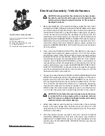
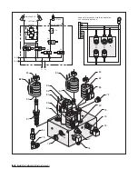
Diode Pack
Mount Bracket

Draw Latch
Toggle Switch
Mount Bracket

The draw latch toggle switch installs through the
rear of the bracket with the protective hood. Align
the key washer with the slot cut in the bracket to
prevent the switch from turning. Secure the
switch with the hardware provided. Note: Use the 
square notch in the bracket (below the protective
hood) to position the braided harness. Use another
cable tie to hold the harness against the bracket.

The Pump Cover Installs Over
The Top Of The Draw Latch
Switch Bracket

To properly secure the pump and manifold cover
on the A-frame, position the cover over the top of
the protective hood on the draw latch switch
mount bracket. Align the holes in the cover with
the U-clips on the welded A-frame tabs. Secure
the cover using two clamping knobs.

Summary of Contents for 680LT

Page 1: ...2004 Assembly Operation Manual Blizzard Straight Blade Snowplow Models 680LT 720LT www blizzardplows com...

Page 2: ...nes and troubleshooting tips Should you need additional information contact your local Blizzard snowplow dealer Their knowledgeable staff is well informed on the latest straight blade information They...

Page 3: ...install on all Blizzard snowplow control stations in minutes Ideal for bucket seat vehicles with low center consoles Pedestal mount accessory shipped with complete hardware and adapter plate Blizzard...

Page 4: ...ing 6 Position snowplow in such a manner as to not block your vision or plow headlights while in transit 7 Do not change the position of the snowplow while in transit 8 Do not exceed 40 mph when trans...

Page 5: ...de stops lifting return the joystick to its neutral position C Angled Right Position To angle your straight blade to the right position the joystick toward the R on the label To stop angling the plow...

Page 6: ...age orientation Please remove these items prior to assembly 4 Place the main blade assembly on a flat level surface Once you have inspected all parts and removed all packaging materials your snowplow...

Page 7: ...e snowplow is lowered with the kickstand in the down position 2 Remove each dust cap from both of the ANGLE CYLINDER ports and attach one 7 16 20 x 7 16 20 MALE O R B CONNECTOR ADAPTER to each port No...

Page 8: ...ropriate fitting illustrated on page 7 in its respective port Note All ports are identified by a stamped number on the manifold The numbers also identify the hydraulic functions which can be ref erenc...

Page 9: ...CAUTION When installing the manifold between the mount brackets on the A frame hold the manifold at the sides of the block Never handle the manifold by the wire lead coils Doing so can cause a solenoi...

Page 10: ...96 to the male connector adapter on port 2 Route the hose under the pump and over the manifold Lastly connect the driver s side angle cylinder hose P N 60294 to port 1 Route the hose over the pump to...

Page 11: ...ution when making the connection Switches can break if done forcefully 5 Continue the harness installation by connecting the PLASTIC FEMALE ELECTRICAL CONNECTOR on the harness to the PLASTIC MALE ELEC...

Page 12: ...WHITE PUMP SOLE NOID ACTIVATION WIRE on the wire harness and position the eyelet over the remaining small terminal on the contactor Secure it with the hardware provided on the solenoid 3 Proceed to c...

Page 13: ...icle head light connector from the headlight Attach the HEADLIGHT ADAPTER CONNECTOR to the existing vehicle headlight connector Next plug the BLACK FIVE PIN CONNECTOR on the headlight adapter into the...

Page 14: ...either end of the light tower Connect the terminals from the plow lights to the terminals on the main lighting harness Repeat the installation for the opposite headlight 15 Align the four mount holes...

Page 15: ...ned Rotate the A frame latch counterclockwise until the latch is locked in the raised position Insert the two HITCH PINS through the mounting holes on the A frame and secure each with one hair pin cot...

Page 16: ...side rear of the moldboard shown below MOUNTING DISMOUNTING INSTRUCTIONS BLZ 1059 TM A Frame Latch Rotates Clockwise And Hooks Onto Draw Pin KEEP FINGERS AW A Y Should the Mounting Dismounting Instruc...

Page 17: ...Notes 15 Notes...

Page 18: ...to grease more frequently depending on your plowing environment 6 Lubricate all pins and bushings to prevent corrosion and to maintain consistent operation including the A frame latch A NLGI Grade 2 m...

Page 19: ...the pump filter and replace the hydraulic oil to within 3 4 from the top of the reservoir Changing the fluid annually will prolong the life of your pump and manifold Never mix different types of hydra...

Page 20: ...e Cylinder Stroke 4 5 8 Ram Diameter 1 Bore Diameter 1 3 4 Plow Headlights Type Low Profile w Turn Signals Measurements 12 W x 5 H x 5 1 4 D Housing Plastic Composite Mount Adjustable Ball Type Bulb T...

Page 21: ...207 Wire Diameter 28 41037 1 1 Bushing Stepped 1 13 O D 0 53 I D x 3 8 Stainless Steel 29 50069 6 6 Pin Clevis 3 4 DIA x 3 YZ 30 61357 8 8 Pin Cotter 1 4 x 1 1 2 Z 31 61434 1 1 Screw Hex Head Cap 1 8...

Page 22: ...pling Nipple 9 16 18 81 60167 2 2 Valve Spool Four Way Two Position C C 86020197 w o screen 82A 62148 1 1 Coil Harness Assembly 1 86 62045 62117 4 82 5 62096 62097 62116 N A 62045 1 1 Connector Electr...

Page 23: ...061 104 61107 1 1 Headlight Plow Driver s Side 105 61108 1 1 Headlight Plow Passenger s Side 106 62032 2 2 Wire Harness with 5 pin plug Plow Headlight N A 62061 2 2 Bulb Sealed Beam Halogen Glass Plow...

Page 24: ...1 97A 97 98 99A 99 100 1 3 4 5A 5 6 9 7 14 10 11 2 12 13 15 16 17 18 19 20 21A 21 22 23 24 25 24 26 27 28 29 29 29 29 29 30 30 30 20 30 31 32 33 34 36 36 37 38 39 40 41 42 43 45A 45 54...

Page 25: ...ranty non Blizzard snowplow service parts or accessories or damage resulting from the use of these unauthorized items Blizzard snowplows are protected by one or more of the following U S patents 5 638...

Page 26: ...1 82 85 86 87 82 83 82 88 78 89 76 A B C D E F G H J K S5 S4 S8 S3 S6 S5 S8 S4 S3 S6 CONNECTS TO PACKARD ELECTRIC CONNECTOR SEE SCHEMATIC ON PAGE 27 N A N A N A N A N A RIGHT ANGLE LEFT ANGLE 3000 PSI...

Page 27: ...SLIDE BOX EXTEND 18 5 RED BLACK RIGHT SLIDE BOX RETRACT 18 6 BLUE WHITE LEFT SLIDE BOX EXTEND 18 7 BLUE BLACK LEFT SLIDE BOX RETRACT 18 8 BLUE LEFT ANGLE 18 9 LT GREEN RIGHT ANGLE 18 10 WHITE LIFT 18...

Page 28: ...LUE G BLUE BLACK H BLUE WHITE J RED BLACK K RED WHITE 1 PLOW HARNESS 2004 WITH MOLDED PLUG P N 62039 NOT DRAWN TO SCALE UNLESS OTHERWISE SPECIFIED ALL DIMENSIONS IN INCHES ALL WIRE 18 GA EXCEPT AS MAR...

Page 29: ...GE RED WHITE WHITE BROWN BROWN HITCH SWITCH DPDT ON OFF ON BROWN PINK BLACK ORANGE WHITE WHITE 10 11 15 3 SEE VEHICLE WIRE HARNESS SCHEMATIC LT GREEN BLUE BLUE BLACK BLUE WHITE RED BLACK RED WHITE RED...

Page 30: ...2 B 2 A YELLOW BLACK B BLACK WHITE C YELLOW D GREEN YELLOW E YELLOW RED A 1 LT GREEN BLACK B 1 BLACK WHITE C 1 LT GREEN D 1 GREEN YELLOW E 1 LT GREEN RED A 2 WHITE B 2 BLACK WHITE C 2 WHITE RED D 2 G...

Page 31: ...A HIGH BEAM YELLOW BLACK F PARK RUN GRAY D RIGHT TURN PINK C GROUND BLACK B A B C D F VEHICLE END VIEW LOOKING AT CONNECTOR E C LT GRN LOW BEAM FEED B YELLOW HIGH BEAM FEED A WHITE RED COMMON D YELLOW...

Page 32: ...ACK 6 BLUE WHITE 7 BLUE BLACK 8 BLUE 9 LT GREEN 10 WHITE 11 ORANGE 15 PINK BLACK HIGH AMP WIRES COLORS PIN 1 BLACK PIN 2 RED WIRE SGT 4 AWG CONDUIT BLACK SLIT 0 50 I D BROWN WHITE 85 LONG RED 8 LONG R...

Page 33: ...E WHITE RED BLACK RED WHT BROWN BLACK GREEN YELLOW NOTE ALL GROUNDS HAVE BLACK WIRE BLACK 15 11 10 9 PINK BLACK 8 7 ORANGE PINK BLACK ORANGE WHITE LT GREEN BLUE BLUE BLACK 6 BLUE WHITE 5 RED BLACK 4 R...

Page 34: ...LAY GROUND FROM SWITCH 18 END VIEW LOOKING AT CONNECTOR 1 2 MOLEX FREE HANGING RECEPTACLE 093 2 PIN POWER CONNECTOR WITH MOLEX FEMALE TERMINAL PIN COLOR FUNCTION AWG NO 1 GREEN YELLOW RELAY GROUND FRO...

Page 35: ...lbs 430 ft lbs 7 8 9 41 550 454 ft lbs 606 ft lbs 1 8 38 600 482 5 ft lbs 640 ft lbs 1 8 54 540 680 ft lbs 900 ft lbs Clamp Loads Pounds Clamp Loads Pounds Nominal Thread Size Nominal Thread Size Gra...

Page 36: ...n the joystick control or wire harness Disconnect the joystick in the cab If the solenoid turns off there is a short in the electrical system Pump runs but plow functions are slow Fluid level in the p...

Page 37: ...illustration below gauge to the tee Push the plow against a solid object and record the pressure reading Note The setting should not exceed 3000 PSI Plow will not angle pump works Review all probable...

Page 38: ...electrical components 4 Snowplows mounted on vehicles other than those for whom Blizzard Corporation has provided a specific undercarriage system 5 Blizzard Corporation does not assume liability for...

Page 39: ...aler 3 Any snowplow or part thereof which has been subject to neglect misuse accident improper installation maintenance or storage This includes but is not limited to corrosion of any electrical compo...

Page 40: ...registered trademarks of Loctite Corporation USA Velcro is a registered trademark of Velcro Industries B V All other trademarks and registered trademarks are the property of their respective owners Al...

Reviews: