


Ref.
Part
Build Quantity Part Description
No.
No.
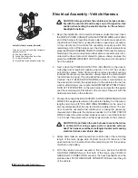
99A 62149
1
1
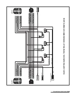
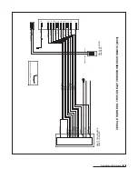
Wire Harness Assembly, Vehicle - Triple Relay Ver: (1) - 99, 100, 62124, 62151, 62056, (3) - 61031, 62016, 62144, (4) - 62072
99
62150
1
1
Wire Harness, Vehicle - Triple Relay Version
100
62000
1
1
Weather Cap, Rubber, Vehicle Wire Harness
N/A
62124
1
1
Fuse, 1/4" DIA. x 1-1/4" BUSS AGC 15A, 32V
N/A
62151
1
1
Main Lighting Harness - Triple Relay Version
N/A
62035
2
2
Weather Cap, Rubber, Main Lighting Harness
N/A
62144
3
3
Headlight Relay, CB1-D-12V, Standard Quick Connect w/Diode Inside
N/A
62042
1
1
Power Contactor (Solenoid), 12V Continuous, High Performance DC, Plastic
N/A
61228
4
4
Nut, Hex Jam, 5/16"- 24 Z
N/A
61229
4
4
Nut, Hex Full, #10 - 32 Z
N/A
61230
2
2
Washer, Split Lock, #10 Z Medium
N/A
62056
1
1
Ground Wire, Power Contactor, 24"
N/A
62072
4
4
Terminal, End Ring, 3/8" I.D. Copper, 4 Gauge
N/A
62008
1
1
Fuse Clip, Mini
N/A
62009
1
1
Fuse Clip, Auto Blade
N/A
62016
3
3
Connector, Splice Lock (18 -14 AWG)
N/A
62126
1
1
Ground Lead (Green/Yellow Wire), 24" with #10 Ring Terminal
N/A
62127
1
1
Switch Lead, On/Off Plow Light (Green/Yellow Wires), 24" with Two 1/4" Receptacles
N/A
62024
1
1
Switch,Toggle, DPDT, On-On, 20 Amps, 125V AC - Plow/Vehicle Headlights
101
61041
1
1
Bracket, Plow/Vehicle Headlight Toggle Switch
102
61088
1
1
Label, Plow/Vehicle Headlight Toggle Switch Bracket (BLZ 1008)
103
61031
5
5
Screw, Hex Washer Self-Drilling, 12-14 x 3/4"
104A 61106
2
2
Headlight Assembly, Plow (Specify Driver’s or Passenger’s Side): (1) - 104/105, 106-110 & 62061
104
61107
1
1
Headlight, Plow, Driver’s Side
105
61108
1
1
Headlight, Plow, Passenger’s Side
106
62032
2
2
Wire Harness (with 5-pin plug), Plow Headlight
N/A
62061
2
2
Bulb, Sealed Beam Halogen, Glass, Plow Headlight (H6545/H4666)
N/A
62062
1
1
Corrosion Preventive Compound (2 fl. oz.)
107
61231
2
2
Adapter, Ball Stud Mount, Headlight
108
61550
2
2
Washer, Neoprene Backing, 1/2" I.D., 1" O.D., Galvanized
109
61112
2
2
Washer, External Tooth Lock, 7/16" YZ
110
61111
2
2
Nut, Hex, 7/16"-14 Grade 8 YZ
111
61427
2
2
Cap, 2-1/4" I.D., 2-3/8" O.D. x 3/4", Black Vinyl
112
39054
1
1
Light Tower
113A 62073
1
1
Control Station Assembly, Joystick: (1) - 113-115
113
62074
1
1
Control Station, Joystick
114
61174
1
1
Label, Control Station, Joystick (BLZ 1017)
115
63106
1
1
Label, Plow Power Switch, On/Off (BLZ 1061)
116
61185
1
1
Base Plate, 1/8" ABS Plastic, Joystick Control Station
117
61127
1
1
Strap (Velcro® with 2" Metal D-Ring), Black, 61"
118
61254
4
4
Screw, Pan Head Machine, 8-32 x 3/4" Z
119
30153
1
1
Undercarriage Weldment, 1997-Current, Chevrolet S-10
120
61128
1
1
Decal, Undercarriage Push Beam, 1-1/2" x 9-1/4" (BLZ 1004)
N/A
61454
1
1
Kit, Hardware, Snowplow Assembly Parts: (1) - 38, 73, 74, (2) - 42, 71, 72, (4) - 16-18, (6) - 29, (7) - 30
N/A
60299
1
1
Kit, Hydraulic Adapter: (1) - 40 & 77, (3) - 36 & 76
N/A
60318
1
1
Kit, Hydraulic Hose: (1) - 34, 35, 39, 41
N/A
61457
1
1
Kit, Hardware, Moldboard Cutting Edge - Models 680LT & 720LT: (6) - 3 & 4
N/A
61458
1
N/A
Cutting Edge (with Hardware Kit), Moldboard - Model 680LT: (1) - 2 (81062), 61457
N/A
61531
N/A
1
Cutting Edge (with Hardware Kit), Moldboard - Model 720LT: (1) - 2 (81073), 61457
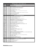
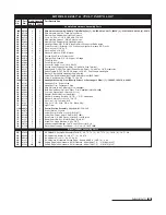
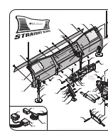
M O D E L S 6 8 0 LT & 7 2 0 LT PA R T S L I S T
Vehicle Wire Harness Assembly Parts
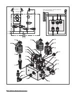
Miscellaneous Assembly Parts
Parts List (3 of 3)
21
680LT
720LT
Summary of Contents for 680LT
Page 17: ...Notes 15 Notes...