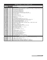


Troubleshooting Guide (2 of 2)
35
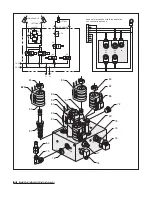
Valve
Jam Nut
Variable Flow
Control Valve
Angle Pressure Relief Valve
Variable Flow Control Valve
Clockwise - Decreases Plow Drop Speed
Counterclockwise - Increases Plow Drop Speed
Problem
Probable Cause(s)
Suggested Remedy
Plow will not lift with magnification to the
Hydraulic lock in the manifold. This occurs if the voltage is
Loosen cartridge valve S6 to relieve pressure and re-
S6 coil.
too low on the coils – should be 11.8 volts.
tighten. DO NOT OVERTIGHTEN! Valves should be
torqued to a maximum of 24 ft. lbs.
Solenoid cartridge valve may be contaminated.
Remove any foreign objects that may be obstructing
proper valve operation. Replace if not operating properly
after cleaning.
Plow will not stay angled when plowing.
The angle pressure relief valve is set too low.
Check the pressure relief by testing the valve inline with
NOTE: Increasing the pressure relief valve will cause
the cylinder. Attach a tee fitting to the angle cylinder
damage to your plow. Do not set the pressure relief
hydraulic adapter and connect the hose and pressure
greater than 3000 PSI (See illustration below)
gauge to the tee. Push the plow against a solid object
and record the pressure reading. Note: The setting should
not exceed 3000 PSI.
Plow will not angle, pump works.
Review all probable causes above.
NOTE: Verify coils S3 & S4 for angle functions.
Plow lowers too slow.
Variable flow control valve is not adjusted properly.
Turn flow control valve counterclockwise in small incre-
(See illustration below)
ments and test. NOTE: Never make adjustments when
the plow is in the raised position! Fluid pressure will make
the valve difficult to adjust and serious injury or death can
occur from a falling plow.
Review all probable causes for plow will not lift (Page 34).
Verify S5 coil (float) or S5 & S8 coils (disconnect) for
magnetism.
Plow drops sporadically.
Variable flow control valve is opened too far.
Turn clockwise 1/16 of a turn and test. See warning above.
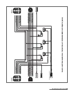
Headlights will not switch from the vehicle to
No power or ground to the headlight relay.
Verify green/yellow (G/Y) wire for the ground is connected.
the snowplow.
Verify black/white (BK/W) wire for the power is connected.
If both are connected properly, replace the headlight relay.
Should your snowplow develop other problems not indicated in the Troubleshooting Guide, contact your local dealer for technical assistance and/or replacement parts.
Summary of Contents for 680LT
Page 17: ...Notes 15 Notes...