115 Volt AC Output
CAUTION – Rechargeable Devices
• Certain rechargeable devices are designed to be charged by plugging them directly into an AC
receptacle. These devices may damage the inverter or the charging circuit.
• When using a rechargeable device, monitor its temperature for the initial ten minutes of use to
determine if it produces excessive heat.
• If excessive heat is produced, this indicates the device should not be used with this inverter.
• This problem does not occur with most battery-operated equipment. Most of these devices use a
separate charger or transformer that is plugged into an AC receptacle.
• The inverter is capable of running most chargers and transformers.
OPERATING INSTRuCTIONS
The Power Inverter must be connected only to batteries with a nominal output voltage of 12 volts.
The unit will not operate from a 6 volt battery and will sustain permanent damage if connected to a
24 volt battery.
Always connect the PI800BB to the 12 volt DC power source before plugging any devices into the unit.
The standard North American 115 volt AC and USB outlets allow simultaneous operation of multiple
devices. Simply plug the equipment into the unit and operate normally. Ensure that the wattage of all
equipment simultaneously plugged into the PI500BB does not exceed 800 watts continuous.
Connection to Power Source
The Power Inverter comes equipped with Battery Clips for connection to a power source.
CONNECTINg TO A POWER SOURCE USINg ThE PROVIDED BATTERY CLIPS
Use the provided Battery Clips (with cables) to connect the Power Inverter directly to the 12 volt
power source as follows:
1. Check to make sure the inverter’s Power Pushbutton has been pressed OFF (no LEDs are lit) and
that no flammable fumes are present in the installation area.
2. Connect the RED cable to the RED post on the back of the inverter. Connect the RED Battery Clip
to the POSITIVE terminal of the battery.
3. Connect the black cable to the black post on the back of the inverter. Connect the black Battery
Clip to the negative terminal of the battery.
4. Make sure that all connections between cables and terminals are secure.
5. Once properly connected to a 12 volt power source and switched on, the green power LED
indicator lights indicating that the inverter is functioning properly.
CAUTIONS
• Do not use with positive ground electrical systems.
• Reverse polarity connection will result in a blown fuse and may cause permanent damage to the
inverter.
Note:
The majority of modern automobiles, RVs and trucks are negative ground.
DIRECT hARDWIRINg TO POWER SOURCE (OPTIONAL CONNECTION METhOD; hARDWARE NOT INCLUDED)
WARNING:
It is not recommended to install with cables longer than 10ft as this can adversely effect
the operation of your inverter.
As this unit can be directly hard wired it has wall mount features built in to secure it in the desired
location. The diagram below shows you how to do this.
INTRODuCTION
Thank you for purchasing the
PI800BB 800 Watt Power Inverter.
This inverter can be used to
recharge 110/120 volt AC devices that have an appropriate recharging adapter with a standard North
American two- or three-prong plug. Please read this Instruction Manual carefully before use to ensure
optimum performance and to avoid damage to this product.
FEATuRES
The unit has 2 LED indicators, 1 to show input conditions and 1 to show output conditions. The input
LED is located beside the power button and the output LED is located on the top of the unit between
the 2 AC outlets. A green LED indicates normal operation, a red LED indicates a fault condition (refer
to Troubleshooting Section of this manual.) and an amber LED indicates low input voltage from the
DC source. The AC outlets are ready to use if you have a green output LED.
The Power Pushbutton turns the inverter ON and OFF. It can also be used to force reset of inverter
circuits by pressing it OFF (no LEDs are lit), then back ON again.
AC power is supplied through two standard North American three-prong type outlets. The outlets can
accommodate either two- or three-pin AC plugs.
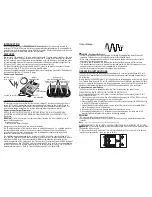
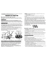
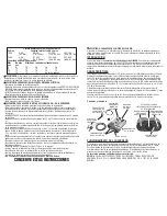
Controls and Functions
HIGH-SPEED CoolInG FanS
Back of Unit
(BlaCk) nEGaTIVE
CaBlE PoST
(RED) PoSITIVE
CaBlE PoST
115 VolT aC ouTlETS
BaTTERy ClIPS
(wITH CaBlES)
ouTPuT
lED InDICaToR
on/oFF
PowER BuTTon
InPuT
lED InDICaToR
HOW THIS INVERTER WORkS
This inverter is an electronic device that converts low voltage DC (direct current) electricity from a
battery to 115 volt AC (alternating current) household power. In designing this inverter, Black &
Decker has incorporated design techniques previously employed in computer power supplies. The
result of these design innovations is a smaller, lighter and easier-to-use power inverter.
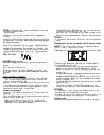
Power Inverter Output Waveform
NOTICE: ThE OUTPUT OF ThIS DEVICE IS NOT SINUSOIDAL. IT hAS A TOTAL hARMONIC
DISTORTION OF 36 PERCENT AND MAXIMUM SINgLE hARMONIC OF 28 PERCENT AT 100%
Rated Load.
IMPORTANT:
This inverter output is not pure-sinusoidal. Therefore this is not suitable for use to
power the following devices:
. Microwave Ovens;
. Transformerless Battery Chargers
Doing so may cause the device to run warmer or overheat.
The AC output waveform of this inverter is known as a modified sine wave. It is a stepped waveform
that has characteristics similar to the sine wave shape of utility power. This type of waveform
is suitable for most AC loads, including linear and switching power supplies used in electronic
equipment, transformers, and small motors.
The modified sine wave produced by this inverter has an RMS (root mean square) voltage of 115
volts. Most AC voltmeters (both digital and analog) are sensitive to the average value of the waveform
rather than the RMS value. They are calibrated for RMS voltage under the assumption that the
waveform measured will be a pure sine wave. These meters will not correctly read the RMS voltage of
a modified sine wave. Non-TRUE RMS meters will read about 20 to 30 volts low when measuring the
output of this inverter. For accurate measurement of the output voltage of this unit, use a TRUE RMS
reading voltmeter such as a Fluke 87, Fluke 8080A, Beckman 4410 or Triplett 4200.

