5
SWITChING ON AND OFF (FIG. I)
dAnGer:
shArp moVinG blAde. neVer ATTempT To
oVerride The operATion of The swiTch As serious
injury could resulT.
Switching on
• Push in and hold the lock-off button (13).
• Pull the bail handle (switch lever) (2) towards the handle.
• Release the lock-off button.
Switching off
• Release the bail handle (switch lever) (2).
wArninG:
Never attempt to lock a switch in the on position.
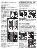
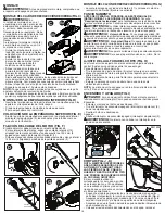
MOWING (FIG. j - K)
noTe: AlwAys inspecT AreA where mower is To be used
And remoVe All sTones, sTicks, wire, bones And oTher
debris which miGhT be Thrown by The roTATinG blAde.
We recommend to use your mower
as outlined in this section in order to
achieve optimum results and to reduce
the risk of cutting the main cable.
• Loop the mains cable through the
cable management system (4) as
shown (fig. j). Ensure you leave
approximately 3 feet (100 cm) of
cable between the switch- box (1)
and the cable management system.
• Ensure that the cable management
system can slide freely from one side
to the other.
• Place the bulk of the cable on the
lawn, close to the
starting point (position 1
in fig. K).
• Switch the mower on as
described above.
• Proceed as shown in
fig. K.
• Move from position 1 to
position 2.
• Turn right, stepping
over the cable and
proceed towards
position 3. The cable
management system
will slide from one side
to the other, ensuring
the cable is kept away
from the cutting blade.
• Turn left, stepping over
the cable and move
towards position 4. The
cable will slide from one
side of the handle to
the other, ensuring the
cable is kept away from
the cutting blade.
• Repeat the above
procedure as required.
wArninG:
Do not
work towards the cable as
shown in fig. j1.
EDGEMAx™ (FIG. L)
EdgeMax™ (7) allows
you to cut grass right up
to the edge of a wall or
fence (fig. L).
EdgeMax™ allows you to
accurately cut grass right
up to the edge of your
lawn (fig. L1).
• With the lawnmower
parallel with the edge of your lawn.
• Push the lawnmower along the edge of the lawn. Ensure that the
EdgeMax™ is slightly over the edge of your lawn (fig. L1)
COMPACT&GO (FIG. M)
When the grass collection box is full, you can compact the grass in the
collection box. You can determine how full the grass collection box is by
looking through the clear grass flap (11).
• Release the bail handle or switch lever (2).
• Using your right foot, press the grass compaction lever (9) all the way
down until it locks into place.
NOTE: The grass in the collection box is now compressed into the rear of the
box. You may continue mowing until the grass collection box becomes full.
EMPTyING ThE GRASS COLLECTION BOx (FIG. M1)
• Release the bail handle or switch lever (2) and unplug the mower.
• Remove the grass collection box (10).
• Empty the contents from the front of the box.
• Place the grass collection box on the ground and pull in and hold the
grass compaction lever release button (14).
• Lift the grass compaction lever (9) into the vertical position and release
the grass compaction lever release button.
• Empty the contents from the rear of the box.
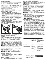
CABLE STORAGE (FIG. N)
The cable holders (5) provide a safe and convenient way to store the
cable when not in use.
• Wrap the cable around the cable holders in a figure eight pattern.
CARRyING ThE MOWER
wArninG:
Rotating blade can cause serious injury. Release bail
handle or switch lever (2) to turn mower off and unplug mower before
lifting, transporting, or storing the mower. Store in a dry place.
• The mower can be carried using the convenient carry handles (10).
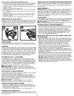
REMOvING BLADE - (FIG. O - P)
wArninG:
Ensure the blade has completely stopped and
disconnect the mower from the power source.
wArninG:
Only use the specified replacement blade: EMB1500
(EM1500 mower) and EMB1700 (EM1700 mower)
• RELEASE BAIL HANDLE OR SWITCH LEVER (2) TO TURN MOWER
OFF, WAIT FOR THE BLADE TO STOP, AND UNPLUG MOWER.
• Cut a piece of 2x4 wood (15) (about 1 foot long) (305 mm) to keep
blade from turning while removing flange nut.
• Turn the appliance onto its side. Wear gloves and proper eye protec-
tion. Be careful of sharp edges of blade.
• Position piece of wood (15) to keep blade from turning as shown in
figure O.
• Use a 9/16 inch wrench (17) to loosen and remove the blade bolt (16)
by turning counterclockwise.
• Pull off blade (18), blade insulator (19), and spacer (20) as shown in
Figure P. Examine all pieces for damage and replace if necessary.
INSTALLING BLADE (FIG. Q)
• Slide the blade onto bolt shaft with
the lettering on the blade facing
out, and place the blade bolt (16)
onto the bolt shaft.
• Tighten the blade bolt as firmly as
possible by hand.
• Position piece of wood (15) to keep
blade from turning as shown in
figure P. Install flange nut with the
flange against the blade spacer
and securely tighten.
• Use a 9/16 inch wrench to securely
tighten the blade bolt by turning the
wrench clockwise.
K
K1
L
L1
j
N
M
M1
14
O
15
17
16
16
19
18
P
20
Q


