background image

4

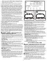
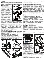
FUNCTIONAL DESCRIPTION (FIG. B)

1.) Switch box   

2.) Bail Handle (EM1700), Switch lever (EM1500)

3.) Handle knobs  

4.) Cable management system

5.) Cable holders  

6.) Height adjustment lever (not shown)

7.) EdgeMax™   

8.) Grass collection box

9.) Compact lever  

10.) Carrying handles

11.) Clear rear flap

ASSEMBLy 

wArninG:

 Before assembly, make sure that the appliance is 

switched off and unplugged.

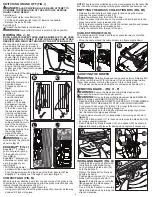
ASSEMBLING ThE GRASS COLLECTION BOx (FIG. C)

wArninG:

 Under normal usage, 

the collection box assembly is subject 

to deterioration and wear and should, 

therefore, be frequently checked for 

replacement. Any replacement 

assembly should be checked for 

compliance with Black and Decker 

recommendations.

The grass box (8) requires assembly 

before use and comes in 5 pieces.

•  Clip the handle (8a) into the lid (8b) 

of the grass box. The handle will only 

fit one way.

•  Clip the 2 sides (8c) of the grass 

collection box together. Make sure 

that all clips and guides are aligned.

•  Align the assembled sides onto the 

bottom (8d) of the grass collection box. 

Ensure that the 4 guides are aligned.

•  Push the 2 parts together. Apply 

even force around all edges of the 

grass collection box securing the 

clips into position uniformly. Check 

that each clip is fastened together securely.

•  Align the lid (8b) onto the assembled grass collection box. Ensure that 

the 10 guides are aligned.

NOTE: Take extra care when aligning the 2 clips at the rear of the grass 

collection box.

•  Push down on the lid to secure all clips. Begin at the back and ensure 

that all clips are securely located.

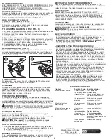
FITTING ThE LOWER hANDLE (FIG. D)

•  Insert the ends of the lower handle into the corresponding holes in the mower.

•  Press the handle down as far as it will go.

•  Secure the handle using the screws.

ASSEMBLING ThE UPPER hANDLE (FIG. E)

•  Fit the upper handle part to the lower handle using the handle storage 

knobs (3), washers and screws as shown.

SECURING ThE MOTOR CABLE (FIG. F)

The motor cable has to be fixed using the cable restraints. 

•  To clip the cable to the handle, snap a restraint clip (10) around the cable 

and upper handle about 6 inches (152.4mm) below the switch box (1).

•  Snap the second restraint clip around the cable and lower handle 

about 6 inches (152.4mm) below the handle knob (3).

FITTING ThE GRASS COLLECTION BOx (FIG. G)

•  Lift the clear grass flap (11) and place the grass collection box (8) over 

the lugs.

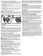
operATion


reAd This insTrucTion mAnuAl And sAfeTy rules before 

operATinG your mower.

 See 

“functional description” 

to famil-

iarize yourself with the location of various controls and adjustments. 

Save this manual for future reference. 

wArninG:


 roTATinG blAdes cAn cAuse serious 

injury. To preVenT serious injury, unpluG mower when 

unATTended, cleAninG, serVicinG, TrAnsporTinG, lifTinG, 

or sTorinG mower.

wArninG:


sharp moving blade

. Do not operate the mower if 

the rear door is not closed under spring tension as serious injury could 

result. Take your mower to the nearest service center for repair.

wArninG:


sharp moving blade

. Never operate the mower 

unless the hanger hooks on the grass catcher are seated properly on 

the mower and the rear discharge door rests firmly against the top of the 

grass catcher as serious injury could result.

wArninG:

 Do not operate mower without collection box (8) attached.

wArninG:

 Let the appliance work at its own pace. Do not overload.

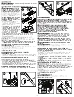
ADjUSTING ThE hEIGhT OF CUT (FIG. h)

The height of cut is adjusted by the central height adjust mechanism, 

there are 6 positions to choose from.

To set the height of cut

•  Pull the height adjustment lever (6) away from the body of the unit.

•  Move the lever towards the rear of the appliance to lower the height of cut.

•  Move the lever towards the front of the appliance to raise the height of cut.

•  Push the height adjustment lever into one of the 6 height locations.

NOTE: The height of cut can be viewed on the height of cut gauge (12) 

on the side of the unit.

D

E

C

8a

8b

8c

8d

6 inches

(152.4 mm)

6 inches

(152.4 mm)

F

10

G

11

1”

1”

2”

2”

3”

3”

h

6

12

I

EM1500

EM1700

13

2

9

1

7

8

10

B

EM1500

2

11

3

4

5

6

Summary of Contents for EM1500

Page 1: ...E OPERACIÓN CENTROS DE SERVICIO Y PÓLIZA DE GARANTÍA ADVERTENCIA LÉASE ESTE INSTRUCTIVO ANTES DE USAR EL PRODUCTO PLEASE READ Before returning this product for any reason If you have a question or experience a problem with your Black Decker purchase go to http www blackanddecker com instantanswers for instant answers 24 hours a day If you can t find the answer or do not have access to the internet...

Page 2: ...logging the discharge guard when leaving the mower or before making any adjustments repairs or inspections 12 Operate mower only in daylight or good artificial light when objects in the path of the blade are clearly visible from the operating area of the mower 13 Do not operate mower while under the influence of alcohol or drugs or when you are tired or ill Always stay alert watch what you are doi...

Page 3: ...electric shock use only with an extension cord suitable for outdoor use such as SW SOW STW STOW SJW SJOW SJTW or SJTOW Use of Extension Cords Make sure the extension cord is in good condition before using Always use the proper size extension cords with the tool that is proper wire size for various lengths of cord and heavy enough to carry the current the tool will draw Use of an undersized cord wi...

Page 4: ... motor cable has to be fixed using the cable restraints To clip the cable to the handle snap a restraint clip 10 around the cable and upper handle about 6 inches 152 4mm below the switch box 1 Snap the second restraint clip around the cable and lower handle about 6 inches 152 4mm below the handle knob 3 Fitting the grass collection box fig G Lift the clear grass flap 11 and place the grass collect...

Page 5: ...ss the grass compaction lever 9 all the way down until it locks into place Note The grass in the collection box is now compressed into the rear of the box You may continue mowing until the grass collection box becomes full Emptying the grass collection box fig M1 Release the bail handle or switch lever 2 and unplug the mower Remove the grass collection box 10 Empty the contents from the front of t...

Page 6: ...rm to the safety standards of the American National Standards Institute and the U S Consumer Product Safety Commission The Blade turns when the motor is running MAINTENANCE Important To assure product SAFETY and RELIABILITY repairs maintenance and adjustment including brush inspection and replacement should be performed by BLACK DECKER Service Centers or other qualified service organizations alway...

Page 7: ...ymbole d alerte à la sécurité indique une situation potentiellement dangereuse qui si elle n est pas évitée peut résulter en des dommages à la propriété Voici une explication des symboles de danger importants sur la tondeuse 1 L utilisateur doit lire et comprendre le mode d emploi 2 Pour réduire le risque de blessures graves ne pas tondre les pentes de haut en bas ou de bas en haut Toujours tondre...

Page 8: ...use et l opération de tonte Ne jamais supposer qu un enfant est resté au dernier endroit où il a été vu 1 Tenir les enfants à l écart de la zone de tonte et sous la surveillance attentive d un adulte responsable autre que l opérateur 2 Rester vigilant et arrêter la tondeuse si un enfant pénètre dans la zone 3 Ne jamais laisser un enfant utiliser la tondeuse 4 Être très prudent aux environs des vir...

Page 9: ...pplication que celle pour laquelle elle a été prévue Un disjoncteur de fuite de terre doit être installé pour protéger les circuits ou les prises utilisés pour la tondeuse à gazon Des prises avec fonction de disjoncteur de fuite de terre intégrées sont aussi disponibles et peuvent être utilisées comme mesures de sécurité AVERTISSEMENT Pour éviter toute décharge électrique utiliser uniquement avec ...

Page 10: ...ande en position marche Assemblage AVERTISSEMENT Avant l assemblage assurez vous que l outil est éteint et débranché Installation du bac de ramassage fig C AVERTISSEMENT Dans des conditions d usage normal le module du collecteur d herbe est susceptible de subir des détériorations et de s user et devrait donc être inspecté fréquemment en vue d un remplacement Tout module de rechange devrait être vé...

Page 11: ...it être utilisé et enlever les pierres des bâtons des fils des os et des débris autre susceptible d être projetés par la lame rotative Nous vous recommandons d utiliser votre tondeuse selon les instructions données dans cette section Vous obtiendrez ainsi le meilleur résultat et réduirez le risque de couper le câble d alimentation Enroulez le câble électrique dans le dispositif de range ment de câ...

Page 12: ...onneux des affûtages plus fréquents seront nécessaires REMPLACER IMMÉDIATEMENT UNE LAME TORDUE OU ENDOMMAGÉE LORS DE L AFFÛTAGE DE LA LAME 1 S assurer que la lame reste équilibrée 2 Affûter la lame suivant l angle de coupe d origine 3 Affûter les arêtes coupantes des deux extrémités de la lame retirer la même quantité de matière aux deux extrémités AFFÛTAGE DE LA LAME DANS UN ÉTAU FIG R 1 S assure...

Page 13: ...roximadamente 3 segundos después de soltar la palanca del interruptor y retirar la llave de seguridad 5 Los objetos golpeados por la hoja de la podadora pueden provocar lesiones graves Manténgase detrás del mango cuando el motor esté en funcionamiento Siempre asegúrese de que las personas y las mascotas estén lejos de la descarga de la podadora mientras esté en funcionamiento Siempre inspeccione e...

Page 14: ...e los vio por última vez 1 Mantenga a los niños fuera del área de trabajo y bajo el cuidado atento de un adulto responsable que no sea el operador 2 Esté atento y apague la podadora si un niño entra al área 3 Nunca permita que los niños operen la podadora 4 Tenga especial cuidado al acercarse a esquinas ciegas arbustos árboles u otros objetos que puedan bloquear su vista de un niño MANTENIMIENTO G...

Page 15: ... el aparato correcto No utilice la podadora de césped para ningún trabajo salvo aquel para el cual se diseñó Se debe contar con la protección de un interruptor de corte por falla a tierra GFCI por sus siglas en inglés en el o los circuitos o tomacorrientes que se utilizarán para la cortadora de césped Existen receptáculos disponibles con protección GFCI incorporada y pueden utilizarse para esta me...

Page 16: ...os resultados óptimos y reducir el riesgo de que se produzca un corte en el cable de alimentación Enganche el cable de alimentación a través del sistema de gestión de cables inteligentes 4 tal como se muestra en la ilustración fig J Asegúrese de que deja aproxi madamente 100 cm de cable entre la caja del interruptor 1 y la fijación de gestión de cables inteligentes Asegúrese de que la fijación del...

Page 17: ...orte del césped La arena hace que la hoja se desafile rápidamente Si su césped tiene un suelo arenoso es probable que se requiera un afilado más frecuente REEMPLACE DE INMEDIATO UNA HOJA DOBLADA O DANADA AL AFILAR LA HOJA 1 Asegúrese de que la hoja se mantenga simétrica 2 Afile la hoja según el ángulo de corte original 3 Afile los bordes de corte en ambos extremos de la hoja retirando la misma can...

Page 18: ...que la hoja se haya detenido y que la llave de seguridad y el paquete de baterías se hayan retirado antes de quitar la hoja 2 Retire la hoja de la podadora Consulte las instrucciones para retirar e instalar la hoja 3 Asegure la hoja 23 en una prensa 24 4 Use guantes y protección adecuada para los ojos y tenga cuidado de no cortarse 5 Lime cuidadosamente los bordes de corte de la hoja con una lima ...

Page 19: ...livia No 605 Col Felipe Carrillo Puerto Cd Madero Tampico Tel 01 833 221 34 50 Perfiles y Herramientas de Morelia Gertrudis Bocanegra No 898 Col Ventura Puente Morelia Michoacán Tel 01 443 313 85 50 Enrique Robles Av de la Solidaridad No 12713 Col La Pradera Irapuato Guanajuato Tel 01 462 626 67 39 Hernández Martinez Jeanette Prolongación Corregidora Nte No 1104 Col Arboledas Queretaro Qro Tel 01 ...

Page 20: ...20 Cat No EM1500 EM1700 Form No 90603028 REV02 January 2014 Copyright 2014 Black Decker Printed in China ...

Reviews: