22
Figure 4.4
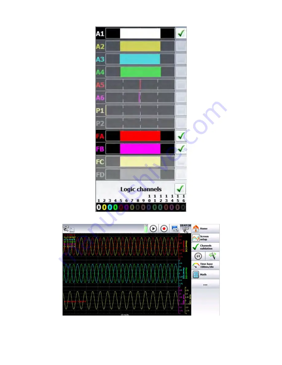
Figure 4.5
You get access to:
www.
GlobalTestSupply
.com
Find Quality Products Online at:
[email protected]
Page 1: ...www GlobalTestSupply com Find Quality Products Online at sales GlobalTestSupply com...
Page 2: ...circuit to be tested which defines the voltage impulses expected and required insulation clearances These categories are Category I CAT I Measurement instruments whose measurement inputs are not inte...
Page 3: ...instrument in the presence of flammable gases or vapors fumes or finely divided particulates The instrument is designed to be used in office type indoor environments Do not operate the instrument In t...
Page 4: ...lways disconnect the power cord from the instrument disconnect all other connections for example test leads computer interface cables etc discharge all circuits and verify there are no hazardous volta...
Page 5: ...connected to a circuit being tested Safety Symbols Symbol Description indicates a hazardous situation which if not avoided will result in death or serious injury indicates a hazardous situation which...
Page 6: ...9 Offset calibration 14 2 10 Default calibration 15 2 11 Screen brightness 15 2 11 1 Locking of the recorder 16 2 12 User mode 16 2 13 Update of the internal software 16 3 Home Screen 17 4 Setup Scre...
Page 7: ...he block is full 45 9 5 1 Creation of the template 45 9 6 Use of the template 46 10 Power Analysis Mode 47 10 1 Power Analysis 47 10 2 Network setup 48 10 3 Wiring and check 49 10 4 Fresnel diagram 50...
Page 8: ...uts 72 14 3 1 Use 72 14 4 Power supply output 72 14 5 External voltage box input output interface 73 15 Ethernet Interface 75 15 1 General 75 15 1 1 Crossover cable 75 15 2 WIFI interface 75 15 3 FTP...
Page 9: ...9 17 Specifications 81 18 LIMITED TWO YEAR WARRANTY 82 19 Service Information 83 www GlobalTestSupply com Find Quality Products Online at sales GlobalTestSupply com...
Page 10: ...nsient Enables complex triggers of the data acquisition action after the end of the data acquisition simulta neous record on file 1 1 3 Go No Go mode Quick acquisition into internal memory of the meas...
Page 11: ...line Current You can make current measurements by shunt between the red and black terminals of the rel evant input In this case select the current type among the parameters of the relevant channel Co...
Page 12: ...al you have to record has low internal impedance use twisted wires For high impedance signal sources using shielded wires is recommended When gathering grounds from the various items on the measuremen...
Page 13: ...2 Storing Printed Recordings In order to maintain the quality of the paper recordings the following is recommended Avoid using laminated sleeves Store away from light in a dry and cool place Store in...
Page 14: ...en light of battery charge will light Charging may be done when it is on or off When the battery is full the green light turns off automatically The recorder can run from AC power indefinitely 2 8 2 S...
Page 15: ...2 10 Default calibration To return the instrument to the factory calibration values use the Recover factory calibration function 1 Go to the setup menu 1 Press 2 Press 2 From setup go to calibration 1...
Page 16: ...other menus available The password is Sefram 2 13 Update of the internal software Software updates to the recorders may be available These updates are available on the Sefram website in the Software U...
Page 17: ...Channel Status 8 Channel Setup 18 Analog Channel Status 9 Triggers 19 Screen Capture Button 10 Channel On Off Menu Figure 3 1 Home Screen Pressing the buttons on screen activates the different modes a...
Page 18: ...18 Figure 3 2 Single Analog Channel Configuration Screen www GlobalTestSupply com Find Quality Products Online at sales GlobalTestSupply com...
Page 19: ...pdate of the internal software Figure 4 1 Setup Screen 1 Language 2 Screen shutoff time setting 3 System time settings 4 Graphic Options The display orientation of the data in the bargraph Item 15 Rig...
Page 20: ...ation 12 Alarm Setup and status of the alarm outputs A B C or D 13 Alarm setup keys 14 Logic channel status and states 15 Bargraph showing live measurements 4 1 Logic channels The 16 logic channels ca...
Page 21: ...ements 1 Screen configuration configuration of the display of measurements on screen Selection of the mode of graphic display F t XY Digital measures full screen Full screen to display the reticule on...
Page 22: ...22 Figure 4 4 Figure 4 5 You get access to www GlobalTestSupply com Find Quality Products Online at sales GlobalTestSupply com...
Page 23: ...to display values of mathematical calculations on screen 4 Access to the channel configuration page Figure 4 6 1 Screen setup configuration of display of measurements on screen Selection of the graphi...
Page 24: ...reen Selection of the mode of graphic display F t XY Digital measures full screen Full screen to display the reticule on the whole screen mode f t Colors to customize the display background reticule c...
Page 25: ...plot and validation of the save in real time Figure 4 9 The program of triggers is different according to the pending mode Direct Memory File or Template See the chapter of the pending mode for more...
Page 26: ...size of the data acquisition to display is big it may take time to recover and display the dots The display is made in 2 phases A quick phase to display the frame of the data acquisition some dots ma...
Page 27: ...ata acquisition shows up at the top of the screen with the pending block number if relevant the current sampling rate the status of the data acquisition stand by pending xx the opening of a save file...
Page 28: ...an USB peripheral Type the name of a new file Create directory creation of a new directory you can type its name with the alphanumerical keyboard displayed on screen Erase erases the selected director...
Page 29: ...ition in Real Time during a data acquisition Manual Available under every mode you can access it from the function after stopping 1 Read block lire un bloc m moire 2 Selection of the block to read 3 R...
Page 30: ...the main menu then The following window pops up Select The following window pops up Select the place and the name of the file to load and display on screen then press Operating software Data acquisiti...
Page 31: ...oftware 6 Display under SeframViewer Launch SeframViewer or double click on a file Open a REC file You can select the channels to display the display mode f t or xy the autocalibration of the channels...
Page 32: ...p files Start and stop records Load data blocks Load files thanks to Windows Explorer through FTP Launch SeframViewer Real time display of data in F t format www GlobalTestSupply com Find Quality Prod...
Page 33: ...d stop conditions of the print Selection of the actions after print and validation of the save in real time Figure 6 1 F t printing a graph as a function of time Digital printing digital values of the...
Page 34: ...simultaneous save File record to a file o Name of the file directory and name of the saving file o Acquisition period sampling rate of the channels o Length of the max file See chapter File mode to k...
Page 35: ...of the print Notes possibility to write notes while printing without at the beginning of the printing on alarm on a length of paper 6 2 1 Relaunching the printing In relaunch mode as soon as stop cond...
Page 36: ...emory Mode Setup 1 Blocks parting of the internal memory in blocks 1 2 4 8 16 32 64 or 128 Erase blocks erasing of all blocks the current block is 1 2 Acquisition period sampling rate of the channels...
Page 37: ...ile mode to know the restrictions of the recording on file 7 2 Sampling period When the frequency of the input signals is too high to record them in Direct mode you must record the measurement signals...
Page 38: ...trigger you will be able to test the trigger during the pre trigger phase in case the trigger should happen before the end of this phase In case of repetitive signals the trigger should be inhibited...
Page 39: ...change of menu Figure 7 3 For longer acquisition time you can zoom onto a part of the data or change of page When changing of menu page you can return to data acquisition by pressing Figure 7 4 Addit...
Page 40: ...le selection of the memory block or of the file to display if there is no valid block the only menu key available will be Load file 2 Screen setup type of display diagrams see chapter Use 3 Time curso...
Page 41: ...igger the number of points per channel in the block a bargraph showing the filling level of the block and the position of the trigger www GlobalTestSupply com Find Quality Products Online at sales Glo...
Page 42: ...ion period sampling speed of the channels internally paced from 1 s to 20min externally paced by the logic channel 16 3 Start start condition of the data acquisition Manual with the key Trigger with a...
Page 43: ...o to create too big files because reading them may be very long It takes ca 3 minutes to read a 200MB file The minimum transfer rate to the flash disk is 100 Kwords s 10 s To know the number of channe...
Page 44: ...d launching of the data acquisition Press Setup of the data acquisition as a template into internal memory Figure 9 1 9 2 Blocks parting of the internal memory in blocks 1 2 4 8 16 32 64 or 128 Erase...
Page 45: ...place for saving data you should reduce the sampling rate or the number of channels See chapter File mode to know the restrictions of the recording on file 9 5 1 Creation of the template Make a data...
Page 46: ...a function of the acquisition speed position of the trigger as a function of pre trigger phase Figure 9 3 The comparison to the template is only possible when the channels are validated for data acqui...
Page 47: ...ower 1 Measurement mode of the current clamp shunt transformer 2 Parameters of the current measurement conversion from the measured value and the value sent to the recorder 3 Nominal current in the ph...
Page 48: ...its external power supply and connected to the socket this for security reasons ensuring earthing 10 2 Network setup In the main menu change of mode by pressing You directly access the setup page Sel...
Page 49: ...associated parameters For clamp primary current secondary voltage these are current voltage clamps For transformer transformer shunt primary and secondary currents and value of the shunt For shunt val...
Page 50: ...ified personal 10 5 Warning messages Messages may appear in red any time at the top of the screen Impossible to synchronize the signal the frequency is wrong the signal is too weak or too noisy Calibe...
Page 51: ...e true shape of the signals hence it will help you detect wiring mistakes The time basis depends on the frequency of the signal at least one alternation You can change the reticules and the position o...
Page 52: ...up Press to open the setup menu Once the device is set up you still have to set the type of measurement to make you can make a power analysis or an energy analysis Figure 10 8 10 9 Parameter acquisiti...
Page 53: ...parameter of a value and of a comparison You will find the list of the parameters you can use at 10 11 You can select a stop condition recording time or manual stop Figure 10 9 10 11 1 Trigger accord...
Page 54: ...ect 10 12 1 Voltage and Current Efficient RMS efficient value o Fund fund efficient value of the fundamental o Average dc average value DC offset o Peak cr maximum value between the max and min peaks...
Page 55: ...hence between 0 and 400V the minimum and maximum values may be changed for finer display For example you will be able to display the signal U1 between 220V and 240V 10 13 Record You launch the data a...
Page 56: ...e Power 1 2 3 Total Reactive Power 1 2 3 Total Apparent Power 2 2 Total Voltage 2 1 2 2 2 3 3 Total Intensity 1 2 3 Power Factor Energy cumulative value of power P this value is reset in the Visualiza...
Page 57: ...this thickness with the thicker keys 1 Checkbox to validate a threshold 2 Current threshold value or change of the threshold value 3 Information about the channel caliber thresholds offset 4 Logic in...
Page 58: ...by pressing on the bargraph of the channel right side of the screen 11 1 Analog channels Figure 11 4 1 Number of the channel 2 Name of the channel give a name to the channel max 26 characters 3 Type s...
Page 59: ...ical to the change of units but instead of giving a couple of dots you give the intercept b and the slope a absolute value square Naperian logarithm square root natural exponential reverse 10 Copy to...
Page 60: ...ignal 5V to 5V period 5s Channel 2 use measurement type V t with the same signal V 10V t 50ms Span 20V s The signal Channel 1 is varying linearly at 4V s and then at 4V s The derivative Channel 2 give...
Page 61: ...Channel 2 use measurement type V dt with the same signal V 10V dt 200 s Span 200Vs The signal integral channel 2 begin at 0Vs and then increase of 10Vs integration of 5V during 2s every signal Channe...
Page 62: ...le if you want to calculate a value of power select the parameters of the A function channel Figure 11 9 You get this page above Then you make the calculation you want by pressing the formula bar and...
Page 63: ...63 Figure 11 10 www GlobalTestSupply com Find Quality Products Online at sales GlobalTestSupply com...
Page 64: ...s trigger only from analogic or logic channels Single Multiple threshold triggering from only one threshold or complex triggering from several channels and several thresholds see description below Suc...
Page 65: ...more or less than the set threshold 4 Threshold value threshold value selected in real value taking the current unit and scale of the configuration of the selected channel into account 5 Edge Selectio...
Page 66: ...s OR 12 1 4 Parasites You can trigger a parasite with a periodic 50Hz signal trigger when the shape of the signal radically changes parasite impulsion 200 s sudden change of frequency Figure 12 4 12 1...
Page 67: ...67 Figure 12 5 www GlobalTestSupply com Find Quality Products Online at sales GlobalTestSupply com...
Page 68: ...t by pressing directly on the type which opens a window with all available calculations 18 various mathematical formulas are available You can display up to 5 simultaneous calculations on screen The d...
Page 69: ...g them to a desired position on screen Minimum Maximum Peak to Peak Low The most frequent value below the median High The most frequent value above the median Amplitude On positive oscillation 100 On...
Page 70: ...ment of the time of 1st positive pulse It is measured at 50 of amplitude Negative pulse width Measurement of the time of 1st negative pulse It is measured at 50 of amplitude Positive duty cycle positi...
Page 71: ...ic channel 9 21 I Logic channel 10 8 I Logic channel 11 20 I Logic channel 12 7 I Logic channel 13 19 I Logic channel 14 6 I Logic channel 15 18 I Logic channel 16 5 Ground 17 Ground 4 Ground 16 O 9 1...
Page 72: ...cquisition clock for the sampling in memory or file mode The data acquisition can then be made up to 500kHz Triggers You can use the logic channels to trigger the plotting and the data acquisitions st...
Page 73: ...the points 1 and 3 of the screw terminal box max usable voltage 48V AC or DC frequency 45 to 440Hz typical trip threshold AC or DC 9V undetected low threshold AC or DC 0 to 2V detected high threshold...
Page 74: ...74 Figure 14 3 www GlobalTestSupply com Find Quality Products Online at sales GlobalTestSupply com...
Page 75: ...and on the device so that the changes are taken into account If you don t have any network administrator Check that the TCP IP driver is correctly installed on your device Case of a PC under Win XP o...
Page 76: ...elect it and validate The commands are automatically positioned You only have to type the password In case of connection problem contact your network administrator Figure 15 2 In the setup page you wi...
Page 77: ...ecording it 15 4 Managing with VNC This piece of software allows you to manage the recorder remotely 15 4 1 Changing the password In the Setup page press VNC You can then change the password of VNC Th...
Page 78: ...ssages made with 3 message units MESSAGE 1 MESSAGE 2 MESSAGE 3 TERM CHANNEL 1 TYPE VOLTAGE DC CALDEC TERM 16 3 Message Syntax A message ex REAR SETUP 1 is made of several fields 16 3 1 Header For the...
Page 79: ...de as messages made of a chain of ASCII characters and possibly of binary bytes with a message termination at the end The format of emission messages is identical to the reception messages although wi...
Page 80: ...ata Made of a chain of ASCII characters starting with a cipher or a sign or They are of NR1 integer NR2 decimal or NR3 type with exponent For example for a digital character 25 02 Text data Any chain...
Page 81: ...stabilization time of 15 minutes over an ambient temperature range of 23 C 5 C 2 Short correction operation performed before making measurement Specifications are subject to change without notice www...
Page 82: ...C to 900 C Power Analysis Function Networks Single phase 3 phase Display Fresnel diagram oscilloscope data Measurements Mean value RMS peak crest factor THD and DF for voltage current active reactive...