background image

16

EDIT SEQUENCE:

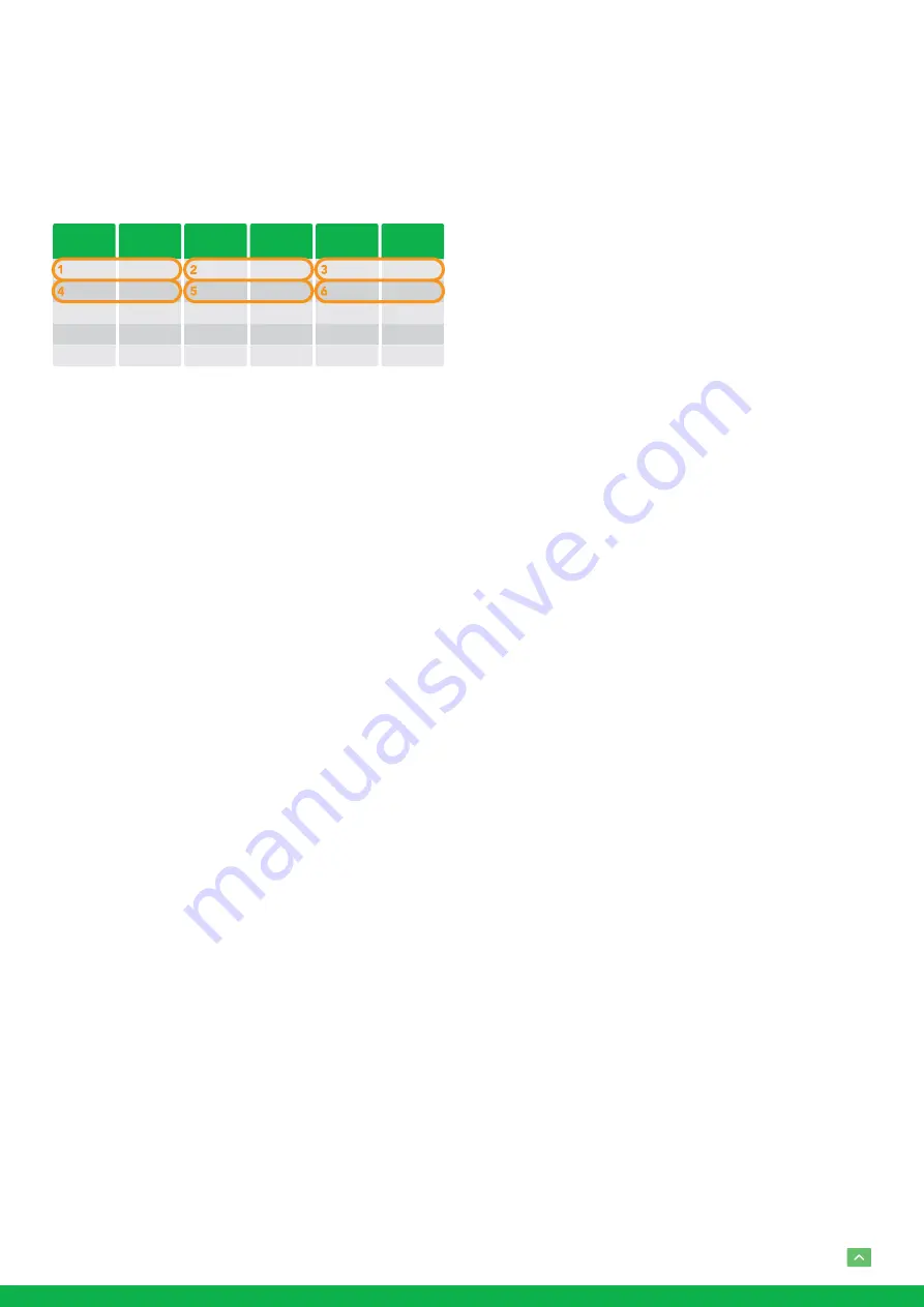
 Set up the above tour.

1. In the order of 1, 2, 3, ... , 6, add each of preset and 

default dwell time to the tour.

2. The tour path will be set based on the presets and 

default dwell have been set in step one.

RUN CONTINOUSELY: 

start the tour has been set.

EXIT: 

Push the joystick to the right to exit this level menu.

PATTERN SETUP: 

A pattern is a memorized, repeating series 

of pan, tilt, zoom, and preset functions that can be recalled 

with a command from a controller or automatically by a pro-

grammed function (alarm, park, event, or power-up). 

The menu is used to manage the patterns. Total of 4 patterns 

can be managed.

PATTERN NUMBER:

 The current pattern number that 

you are managing.

RECORD NEW PATTERN:

 Set up the above pattern.

1. Push the joystick to the right to enter this setting menu.

2. Move the camera to the start position you want, and 

then call the preset 1 to save.

3. Move the camera to each position you want to record 

the pattern, and then call the preset1 to end.

4. Finished.

RUN CONTINIUSELY

: start the above pattern.

EXIT: 

Push the joystick to the right to exit this level menu.

SCAN SETUP:

 The menu is used to manage the scans. Total 

of 4 scans can be manage.

PANNING NUMBER: 

The current scan number that you 

are managing.

SET LEFT LIMET: 

Set the left limit of the camera scan.

1. Push the joystick to the right to enter this setting menu.

PRESET

NUMBER

000
000
000
000

...

DEFAULT

DWELL

000
000
000
000

...

PRESET

NUMBER

000
000
000
000

...

DEFAULT

DWELL

000
000
000
000

...

PRESET

NUMBER

000
000
000
000

...

DEFAULT

DWELL

000
000
000
000

...

2. Move the camera to the left limit position that you 

want, and then call the preset 1 to save.

SET RIGHT LIMET:

 Set the right limit of the camera scan.

1. Push the joystick to the right to enter this setting menu.

2. Move the camera to the right limit position that you 

want, and then call the preset 1 to save.

DEFAULT SPEED: Set the interval time from left to right 

during Scanning, and select value from 3 to 255 sec.

RUN CONTINOUSELY:

 start the above scan.

EXIT:

 Push the joystick to the right to exit this level menu.

IDLE TIMER:

 If the camera stays in No-operation for certain 

amount of IDLE Time, the camera would take action auto-

matically.

The menu is used to set the IDLE time, and value can be se-

lected from 0 to 255 sec.

IDLE ACTION:

 After the IDLE time, the camera starts the 

IDLE action automatically.

Even if the idle time’s value is set to 0, or during the IDLE 

time, manual operation will always have the priority to the 

response.

The menu is used to select the IDLE action.

The IDLE action can be selected from: OFF, PRESET1-220, 

SCAN1-4, TOUR1-4, PATT1-4.

EXIT:

 Push the joystick to the right to exit this level menu.

EXIT

Push the joystick to the right to exit the menu. All the setting 

modifications will be saved.

Summary of Contents for NDI EYES A300

Page 1: ...USER MANUAL PART 1 FULL NDI NO COMPROMISES EYES A300...

Page 2: ...g the Camera 8 Wall Mount 9 Laser Illuminator 9 Use SDI video output 10 Starting the Camera 10 Setup Camera ID Baud Rate and Control Protocol 10 Controlling the Camera 11 Adjusting and Setting with Me...

Page 3: ...her trademarks company names and product names contained in this manual are the property of their respective owners IMPORTANT INFORMATION Legal Notice Attention To ensure account security please chang...

Page 4: ...erein may result in hazardous laser emissions Maintenance Precautions If there is dust on the front glass surface remove the dust gently using an oil free brush or a rubber dust blowing ball If there...

Page 5: ...rs IR ON OFF is available Outdoor Environmental Rating IP67 Corrosion Resistant Treatment Various Image Functionalities WDR BLC Defog Day Night Supports 120 tilt 360 pan range adaptive speed up to 150...

Page 6: ...arm Inputs x2 Data Cable Alarm Output x1 SDI Signal CAMERA SIDE CONTROL SIDE 1 IR Laser illuminator 2 Lens 3 Nitrogen Filled Housing Valves NOTE Nitrogen filled Valves for factory use only Do not open...

Page 7: ...and the clamp of the cable connector is intact SDI Signal Cable In order to ensure the quality of the installation of the project the HD SDI and 3G SDI signals have a high data transmission rate of di...

Page 8: ...d the pendant mount bracket may be necessary during mounting For their model refer to the accessory list recommended by your dealer The wall bearing capacity and the bracket length must meet all onsit...

Page 9: ...m the camera when the laser is working 6 When the IR laser is operating do not look directly into the laser beam or obstruct the pathway of the beam 7 Everyone who uses a laser should be aware of the...

Page 10: ...ction TX TX RX RS 485 A RS 485 RS 485 D RX RS 485 B RS 485 RS 485 D 1 2 RS422 VISCA control connection diagram SONY Keyboard RS422 Connection VISCA None Sony Keyboard RS422 Connection Setup Camera ID...

Page 11: ...match the control system or keyboard camera ID and Baud Rate setting to the cameras PTZ Control 1 8 9600 None None 1 PELCO D Port Mode Stop Bits Data Bits Baud Rate Flow Control Parity Address Code PT...

Page 12: ...ake the subject appear clearer This is set to ON OFF WIDE D Wide dynamic range mode ON OFF The cam era distinguishes light and dark areas within the same scene adjusts the brightness for dark areas an...

Page 13: ...form manual A F RECOVER TIME When the camera is not in operation if in the manual focus mode after the A F RECOVER TIME it will automatically transfer to the automatic focus If the time is 0 then the...

Page 14: ...erwise the camera and keyboard and IP control will be unable to communicate FLIP Select ON to flip the image if you need to lift the camera VIDEO FORMAT SDI IP True Dual Output You can have parallel S...

Page 15: ...resets still store camera positions and image parameters but 17 128 presets will only store camera positions You can set the presets to number 17 128 if you don t want the preset to memorize the image...

Page 16: ...e camera scan 1 Push the joystick to the right to enter this setting menu PRESET NUMBER 000 000 000 000 DEFAULT DWELL 000 000 000 000 PRESET NUMBER 000 000 000 000 DEFAULT DWELL 000 000 000 000 PRESET...

Page 17: ...17 Dimensions Unit mm 423 183 118 8 118 8 4 5 16 18 UNC 20...

Page 18: ...18...

Page 19: ...19...

Page 20: ...WELCOME TO THE FUTURE bird dog tv hello bi rd dog tv...

Reviews: