BL-CB33-0115 - 03-01-2018
1-1
SECTION 1
DESCRIPTION
1-1. INTRODUCTION.
This publication describes the 24 volt CB33 lift truck
manufactured by Big Lift LLC. Included are operating
instructions, planned maintenance instructions, lubri-
cation procedures, corrective maintenance procedures
and a complete parts list with part location illustrations.
Users shall comply with all requirements indicated in
applicable OSHA standards and current edition of
A.N.S.I. B56.1 Part II. By following these requirements
and the recommendations contained in this manual,
you will receive many years of dependable service
from your CB33 lift truck.
1-2. GENERAL DESCRIPTION.
The self-propelled CB33 truck,
, lifts and
transports payloads up to 3300 pounds on adjustable
forks.
The forward and reverse motion is controlled by either
of two thumb controlled levers mounted on the control
head. Stopping and turning is controlled by the control
arm. Lift, Lower and Tilt are controlled by pushbuttons
on the control head. The battery powered lift truck is
quiet and without exhaust fumes.
The reversible AC motor propels the lift truck in for-
ward or reverse direction throughout the available
speed range. The CB33 lift truck can be driven with
forks raised or lowered; however, the speed is
restricted when the platform is raised above a preset
limit.
On demand power steering makes the lift truck highly
maneuverable.
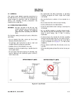
The model number will be found on the name plate
(
) along with the serial number, lifting capac-
ity, and load center.
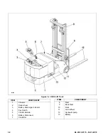
shows the locations of
the truck’s main components and controls.
1-3. SAFETY FEATURES.
The CB33 is designed and engineered to provide max-
imum safety for operator and payload. Some of the
safety features incorporated into the design are:
• Dead-man brake to apply the brake and cut off drive
power when the control arm is released.
Figure 1-1 Name Plate
• Belly-button switch to reverse truck should the oper-
ator accidentally pin himself against a wall or
obstruction when backing up in slow speed.
• High speed limit switch to restrict speed when lift
carriage is raised above the preset limit.
• All control functions automatically return to “OFF”
when released.
• Externally accessible quick-disconnect battery plug
within operator's reach.
• Separately fused control circuits and power circuits.
• Readily accessible horn button.
• Lift carriage backrest to help stabilize the load.
• Handle to provide a firm hand hold for operator.
• Flow control valve regulates maximum lowering
speed within prescribed limits.
• Relief valve maintains hydraulic pressure within pre-
scribed limits.
• High visibility color scheme of truck provides visual
alert of truck’s presence.
• Battery Indicator.
R6209
COMPLIES WITH THE APPLICABLE REQUIRE-
COMPLIES WITH THE APPLICABLE REQUIRE-
MENTS OF ANSI B56.1 AND OSHA STANDARDS
MENTS OF ANSI B56.1 AND OSHA STANDARDS
BIG LIFT LLC
BIG LIFT LLC
WISCONSIN DELLS, WISCONSIN 53965
WISCONSIN DELLS, WISCONSIN 53965
AUSTRALIAN PATENT NO. 537,987
AUSTRALIAN PATENT NO. 537,987
U.S. PATENT NO. 4,444,284
U.S. PATENT NO. 4,444,284
TRUCK
TYPE
MODEL NO.
SERIAL NO.
VOLTAGE
BATTERY
TYPE
TYPE
CERTIFIED
MAX CAP LB/
MAX CAP LB/
LOAD CTR IN/
LOAD CTR IN/
LIFT HGT IN/
LOAD CTR IN/
LOAD CTR IN/
LIFT HGT IN/
ALT CAP LB/
BATTERY MIN WT LB/
BATTERY MIN WT LB/
TRUCK WT LESS BATTERY LB/
TRUCK WT LESS BATTERY LB/
BATTERY MAX WT LB/
BATTERY MAX WT LB/
TRUCK WT WITH BATTERY LB/
TRUCK WT WITH BATTERY LB/
KG
MM
MM
MM
MM
KG
KG
KG
KG
KG
Summary of Contents for CB33
Page 9: ...BL CB33 0115 03 01 2018 2 3 Figure 2 2 Sample of Operator Check List R6479...
Page 12: ...2 6 BL CB33 0115 03 01 2018 NOTES...
Page 18: ...3 6 BL CB33 0115 03 01 2018 NOTES...
Page 38: ...4 20 BL CB33 0115 03 01 2018 NOTES...
Page 44: ...5 6 BL CB33 0115 03 01 2018 NOTES...
Page 46: ...6 2 BL CB33 0115 03 01 2018 Figure 6 1 Drive Assembly DP_0004...
Page 48: ...7 2 BL CB33 0115 03 01 2018 Figure 7 1 Drive Assembly DP_0004...
Page 49: ...BL CB33 0115 03 01 2018 7 3 Figure 7 2 Load Wheels DP_0007...
Page 50: ...7 4 BL CB33 0115 03 01 2018 NOTES...
Page 52: ...8 2 BL CB33 0115 03 01 2018 Figure 8 2 Elevation System Telescopic DP_0008...
Page 54: ...8 4 BL CB33 0115 03 01 2018 Figure 8 3 Mast Three Stage Mast DP_0009...
Page 56: ...8 6 BL CB33 0115 03 01 2018 NOTES...
Page 58: ...9 2 BL CB33 0115 03 01 2018 Figure 9 1 Hydraulic System DP_0018...
Page 60: ...9 4 BL CB33 0115 03 01 2018 Figure 9 3 Elevation System Telescopic DP_0008...
Page 66: ...9 10 BL CB33 0115 03 01 2018 Figure 9 8 Secondary Lift Cylinder Three Stage Mast DP_0012...
Page 69: ...BL CB33 0115 03 01 2018 9 13 Figure 9 10 Tilt Cylinder DP_0016...
Page 70: ...9 14 BL CB33 0115 03 01 2018 NOTES...
Page 72: ...10 2 BL CB33 0115 03 01 2018 Figure 10 1 Electrical System R6478 DP_0022...
Page 73: ...BL CB33 0115 03 01 2018 10 3 Figure 10 2 Electrical Panel R6478 DP_0023...
Page 75: ...BL CB33 0115 03 01 2018 10 5 Figure 10 3 Transmission Motor Brake Assembly DP_0004...
Page 76: ...10 6 BL CB33 0115 03 01 2018 NOTES...
Page 77: ...BL CB33 0115 03 01 2018 11 1 SECTION 11 OPTIONAL EQUIPMENT...
Page 78: ...11 2 BL CB33 0115 03 01 2018 NOTES...
Page 80: ...12 2 BL CB33 0115 03 01 2018 Figure 12 1 Steering System DP_0001...
Page 82: ...12 4 BL CB33 0115 03 01 2018 Figure 12 1 Steering System Continued DP_0001...
Page 84: ...12 6 BL CB33 0115 03 01 2018 Figure 12 2 Control Head DPP_0002...
Page 86: ...12 8 BL CB33 0115 03 01 2018 Figure 12 3 Control Head when Side Shift option DP_0035...
Page 88: ...12 10 BL CB33 0115 03 01 2018 Figure 12 4 Drive System DP_0003...
Page 90: ...12 12 BL CB33 0115 03 01 2018 Figure 12 5 Drive Assembly Used up to serial S2410419 DP_0004...
Page 94: ...12 16 BL CB33 0115 03 01 2018 Figure 12 7 Drive Assembly Used from serial 325130601 DP_0032...
Page 104: ...12 26 BL CB33 0115 03 01 2018 Figure 12 10 Compartment DP_0005...
Page 106: ...12 28 BL CB33 0115 03 01 2018 Figure 12 11 Frame DP_0006...
Page 108: ...12 30 BL CB33 0115 03 01 2018 Figure 12 11 Frame Continued DP_0006...
Page 110: ...12 32 BL CB33 0115 03 01 2018 Figure 12 12 Load Wheels DP_0007...
Page 112: ...12 34 BL CB33 0115 03 01 2018 Figure 12 13 Elevation System Telescopic DP_0008...
Page 114: ...12 36 BL CB33 0115 03 01 2018 Figure 12 13 Elevation System Telescopic Continued DP_0008...
Page 116: ...12 38 BL CB33 0115 03 01 2018 Figure 12 14 Elevation System Three Stage Mast DP_0009...
Page 118: ...12 40 BL CB33 0115 03 01 2018 Figure 12 14 Elevation System Three Stage Mast Continued DP_0009...
Page 124: ...12 46 BL CB33 0115 03 01 2018 Figure 12 16 Lift Carriage Three Stage Mast DP_0014...
Page 126: ...12 48 BL CB33 0115 03 01 2018 Figure 12 17 Side Shift Assembly DP_0034...
Page 128: ...12 50 BL CB33 0115 03 01 2018 Figure 12 18 Chain Assembly DP_0017...
Page 134: ...12 56 BL CB33 0115 03 01 2018 Figure 12 21 Hydraulic System Used with Side Shift DP_0036...
Page 136: ...12 58 BL CB33 0115 03 01 2018 Figure 12 22 Tilt System DP_0015...
Page 138: ...12 60 BL CB33 0115 03 01 2018 Figure 12 23 Lift System Telescopic Not with Side Shift DP_0019...
Page 140: ...12 62 BL CB33 0115 03 01 2018 Figure 12 24 Lift System Telescopic With Side Shift DP_0037...
Page 146: ...12 68 BL CB33 0115 03 01 2018 Figure 12 26 Lift Cylinder Telescopic DP_0010...
Page 148: ...12 70 BL CB33 0115 03 01 2018 Figure 12 27 Free Lift Cylinder Three Stage Mast DP_0011...
Page 150: ...12 72 BL CB33 0115 03 01 2018 Figure 12 28 Secondary Lift Cylinder Three Stage Mast DP_0012...
Page 156: ...12 78 BL CB33 0115 03 01 2018 Figure 12 31 Pump and Motor Not when Side Shift DP_0021...
Page 158: ...12 80 BL CB33 0115 03 01 2018 Figure 12 32 Pump and Motor When Side Shift DP_0039...
Page 160: ...12 82 BL CB33 0115 03 01 2018 Figure 12 33 Electrical System ELECTRICAL SYSTEM DP_0022...
Page 162: ...12 84 BL CB33 0115 03 01 2018 Figure 12 34 Electrical Panel DP_0023...
Page 168: ...12 90 BL CB33 0115 03 01 2018 Figure 12 37 Wiring Cables DP_0025...
Page 170: ...Big Lift LLC...


