


BL-CB33-0115 - 03-01-2018
5-3
5-1.3. Control Head Removal.
1.
Remove the cap assembly as described in para-
graph
2.
Tag and disconnect harness from switch and
potentiometer.
3.
Hold control head in place and remove three
screws, lock washers and flat washers. Remove
control head from bracket.
5-1.4. Control Head Installation.
1.
Hold control head in place and secure to bracket
with three screws, lock washers and flat washers .
2.
Reconnect harness to switch and potentiometer.
3.
Install the cap assembly as described in para-
graph
5-1.5. Speed Potentiometer Replacement.
1.
Remove the cap assembly as described in para-
graph
2.
Disconnect harness from potentiometer.
3.
Remove screw, washer and travel control from
potentiometer.
4.
Remove screw, washer and travel control from
other side of potentiometer.
5.
Remove potentiometer from cover.
6.
Position new potentiometer in cover.
7.
Install travel control on potentiometer and secure
with screw, and washer.
8.
Install travel control on the other side of potenti-
ometer and secure with screw, and washer.
9.
Connect harness to potentiometer.
10. Install the cap assembly as described in para-
graph
5-1.6. Belly-Button Switch Replacement.
1.
Remove the cap assembly as described in para-
graph
2.
Disconnect harness from switch.
3.
Remove and replace switch.
4.
Reconnect harness to switch.
5.
Install the cap assembly as described in para-
graph
5-1.7. Horn Switch Replacement.
1.
Remove the cap assembly as described in para-
graph
2.
Remove two screws, two mounts and horn button
.
3.
Remove switch from cap.
4.
Position the new switch in cap.
5.
Position horn button in cap and secure with two
mounts and two screws.
6.
Install the cap assembly as described in para-
graph
5-1.8. Lift and Lower Switch Replacement.
1.
Remove the cap assembly as described in para-
graph
2.
Remove switch assembly from cap.
3.
Install new switch assembly in cap.
4.
Install the cap assembly as described in para-
graph
5-1.9. Tilt Switch Replacement.
1.
Remove the cap assembly as described in para-
graph
2.
Remove two screws and switch assembly form
button.
3.
Secure new switch assembly to button with two
screws.
4.
Install the cap assembly as described in para-
graph
5-2. CONTROL ARM
5-2.1. Gas Return Spring Replacement.
The control arm gas return spring is replaced while the
control arm is in the upright position.
1.
Turn off the key switch and disconnect the batter-
ies.
2.
Remove three screws, lock washers, flat washers
and cover.
3.
Secure the control arm in the upright position.
4.
Remove screw and free the gas return spring
from bracket.
5.
Pull downward on the gas return spring to free it
from its seat inside control arm.
6.
Position the new gas return spring inside the con-
trol arm being sure it fully engages its seat.
7.
Position the opposite end of the gas return spring
on bracket and install screw.
8.
Install cover and secure with three screws, lock
washers, flat washers
Summary of Contents for CB33
Page 9: ...BL CB33 0115 03 01 2018 2 3 Figure 2 2 Sample of Operator Check List R6479...
Page 12: ...2 6 BL CB33 0115 03 01 2018 NOTES...
Page 18: ...3 6 BL CB33 0115 03 01 2018 NOTES...
Page 38: ...4 20 BL CB33 0115 03 01 2018 NOTES...
Page 44: ...5 6 BL CB33 0115 03 01 2018 NOTES...
Page 46: ...6 2 BL CB33 0115 03 01 2018 Figure 6 1 Drive Assembly DP_0004...
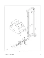
Page 48: ...7 2 BL CB33 0115 03 01 2018 Figure 7 1 Drive Assembly DP_0004...
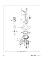
Page 49: ...BL CB33 0115 03 01 2018 7 3 Figure 7 2 Load Wheels DP_0007...
Page 50: ...7 4 BL CB33 0115 03 01 2018 NOTES...
Page 52: ...8 2 BL CB33 0115 03 01 2018 Figure 8 2 Elevation System Telescopic DP_0008...
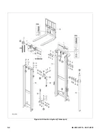
Page 54: ...8 4 BL CB33 0115 03 01 2018 Figure 8 3 Mast Three Stage Mast DP_0009...
Page 56: ...8 6 BL CB33 0115 03 01 2018 NOTES...
Page 58: ...9 2 BL CB33 0115 03 01 2018 Figure 9 1 Hydraulic System DP_0018...
Page 60: ...9 4 BL CB33 0115 03 01 2018 Figure 9 3 Elevation System Telescopic DP_0008...
Page 66: ...9 10 BL CB33 0115 03 01 2018 Figure 9 8 Secondary Lift Cylinder Three Stage Mast DP_0012...
Page 69: ...BL CB33 0115 03 01 2018 9 13 Figure 9 10 Tilt Cylinder DP_0016...
Page 70: ...9 14 BL CB33 0115 03 01 2018 NOTES...
Page 72: ...10 2 BL CB33 0115 03 01 2018 Figure 10 1 Electrical System R6478 DP_0022...
Page 73: ...BL CB33 0115 03 01 2018 10 3 Figure 10 2 Electrical Panel R6478 DP_0023...
Page 75: ...BL CB33 0115 03 01 2018 10 5 Figure 10 3 Transmission Motor Brake Assembly DP_0004...
Page 76: ...10 6 BL CB33 0115 03 01 2018 NOTES...
Page 77: ...BL CB33 0115 03 01 2018 11 1 SECTION 11 OPTIONAL EQUIPMENT...
Page 78: ...11 2 BL CB33 0115 03 01 2018 NOTES...
Page 80: ...12 2 BL CB33 0115 03 01 2018 Figure 12 1 Steering System DP_0001...
Page 82: ...12 4 BL CB33 0115 03 01 2018 Figure 12 1 Steering System Continued DP_0001...
Page 84: ...12 6 BL CB33 0115 03 01 2018 Figure 12 2 Control Head DPP_0002...
Page 86: ...12 8 BL CB33 0115 03 01 2018 Figure 12 3 Control Head when Side Shift option DP_0035...
Page 88: ...12 10 BL CB33 0115 03 01 2018 Figure 12 4 Drive System DP_0003...
Page 90: ...12 12 BL CB33 0115 03 01 2018 Figure 12 5 Drive Assembly Used up to serial S2410419 DP_0004...
Page 94: ...12 16 BL CB33 0115 03 01 2018 Figure 12 7 Drive Assembly Used from serial 325130601 DP_0032...
Page 104: ...12 26 BL CB33 0115 03 01 2018 Figure 12 10 Compartment DP_0005...
Page 106: ...12 28 BL CB33 0115 03 01 2018 Figure 12 11 Frame DP_0006...
Page 108: ...12 30 BL CB33 0115 03 01 2018 Figure 12 11 Frame Continued DP_0006...
Page 110: ...12 32 BL CB33 0115 03 01 2018 Figure 12 12 Load Wheels DP_0007...
Page 112: ...12 34 BL CB33 0115 03 01 2018 Figure 12 13 Elevation System Telescopic DP_0008...
Page 114: ...12 36 BL CB33 0115 03 01 2018 Figure 12 13 Elevation System Telescopic Continued DP_0008...
Page 116: ...12 38 BL CB33 0115 03 01 2018 Figure 12 14 Elevation System Three Stage Mast DP_0009...
Page 118: ...12 40 BL CB33 0115 03 01 2018 Figure 12 14 Elevation System Three Stage Mast Continued DP_0009...
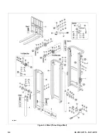
Page 124: ...12 46 BL CB33 0115 03 01 2018 Figure 12 16 Lift Carriage Three Stage Mast DP_0014...
Page 126: ...12 48 BL CB33 0115 03 01 2018 Figure 12 17 Side Shift Assembly DP_0034...
Page 128: ...12 50 BL CB33 0115 03 01 2018 Figure 12 18 Chain Assembly DP_0017...
Page 134: ...12 56 BL CB33 0115 03 01 2018 Figure 12 21 Hydraulic System Used with Side Shift DP_0036...
Page 136: ...12 58 BL CB33 0115 03 01 2018 Figure 12 22 Tilt System DP_0015...
Page 138: ...12 60 BL CB33 0115 03 01 2018 Figure 12 23 Lift System Telescopic Not with Side Shift DP_0019...
Page 140: ...12 62 BL CB33 0115 03 01 2018 Figure 12 24 Lift System Telescopic With Side Shift DP_0037...
Page 146: ...12 68 BL CB33 0115 03 01 2018 Figure 12 26 Lift Cylinder Telescopic DP_0010...
Page 148: ...12 70 BL CB33 0115 03 01 2018 Figure 12 27 Free Lift Cylinder Three Stage Mast DP_0011...
Page 150: ...12 72 BL CB33 0115 03 01 2018 Figure 12 28 Secondary Lift Cylinder Three Stage Mast DP_0012...
Page 156: ...12 78 BL CB33 0115 03 01 2018 Figure 12 31 Pump and Motor Not when Side Shift DP_0021...
Page 158: ...12 80 BL CB33 0115 03 01 2018 Figure 12 32 Pump and Motor When Side Shift DP_0039...
Page 160: ...12 82 BL CB33 0115 03 01 2018 Figure 12 33 Electrical System ELECTRICAL SYSTEM DP_0022...
Page 162: ...12 84 BL CB33 0115 03 01 2018 Figure 12 34 Electrical Panel DP_0023...
Page 168: ...12 90 BL CB33 0115 03 01 2018 Figure 12 37 Wiring Cables DP_0025...
Page 170: ...Big Lift LLC...