


BL-CB33-0115 - 03-01-2018
4-7
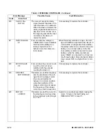
Table 4-2 TRACTION CONTROLLER - Continued
Error Message
Possible Cause
Fault Elimination
Code
Error Text
65
BATTERY LOW
This occurs when the battery
charge is calculated being less
than or equal to 10% of the full
charge and the BATTERY
CHECK setting is other than 0
(refer to SET OPTION menu).
Charge the battery. If charging does not help,
using a voltmeter, measure the battery volt-
age and compare the reading with the
value in the BATTERY VOLTAGE parame-
ter. If they are different, adjust the value of
the ADJUST BATTERY function.
71
EEPROM KO
This is due to a HW or SW defect
of the non-volatile embedded
memory supporting the control-
ler parameters. This alarm
does not inhibit the machine
operations, but the truck will
work with the default values.
Try to execute a CLEAR EEPROM operation
(refer to CONSOLE manual). Switch the
key off and on to check the result. If the
alarm occurs permanently, it is necessary
to replace the controller. If the alarm disap-
pears, the previously stored parameters will
have been replaced by the default parame-
ters.with the temperature increases from
85
to 105
65
MOTOR
TEMPERATURE
This warning occurs when the
temperature sensor is opened
(If digital) or has overtaken the
threshold of 150
C (if analog).
Check the thermal sensor inside the motor
(use the MOTOR TEMPERATURE reading
in the TESTER menu); check the sensor
ohmic value and sensor wiring. If the sen-
sor is OK, improve the air cooling of the
motor. If the warning is present when the
motor is cool, then the problem is inside the
controller.
61
THERMIC SEN-
SOR KO
The output of the controller ther-
mal sensor is out of range.
This type of fault is not related to external
components; replace the controller.
CHECK UP
NEEDED
This is just a warning to call for
the time programmed mainte-
nance
It is just enough to turn the CHECK UP DONE
option to level ON after the maintenance is
executed.
DATA
ACQUISITION
Acquisition of the current gains.
The alarm ends when the acquisition is done.
Summary of Contents for CB33
Page 9: ...BL CB33 0115 03 01 2018 2 3 Figure 2 2 Sample of Operator Check List R6479...
Page 12: ...2 6 BL CB33 0115 03 01 2018 NOTES...
Page 18: ...3 6 BL CB33 0115 03 01 2018 NOTES...
Page 38: ...4 20 BL CB33 0115 03 01 2018 NOTES...
Page 44: ...5 6 BL CB33 0115 03 01 2018 NOTES...
Page 46: ...6 2 BL CB33 0115 03 01 2018 Figure 6 1 Drive Assembly DP_0004...
Page 48: ...7 2 BL CB33 0115 03 01 2018 Figure 7 1 Drive Assembly DP_0004...
Page 49: ...BL CB33 0115 03 01 2018 7 3 Figure 7 2 Load Wheels DP_0007...
Page 50: ...7 4 BL CB33 0115 03 01 2018 NOTES...
Page 52: ...8 2 BL CB33 0115 03 01 2018 Figure 8 2 Elevation System Telescopic DP_0008...
Page 54: ...8 4 BL CB33 0115 03 01 2018 Figure 8 3 Mast Three Stage Mast DP_0009...
Page 56: ...8 6 BL CB33 0115 03 01 2018 NOTES...
Page 58: ...9 2 BL CB33 0115 03 01 2018 Figure 9 1 Hydraulic System DP_0018...
Page 60: ...9 4 BL CB33 0115 03 01 2018 Figure 9 3 Elevation System Telescopic DP_0008...
Page 66: ...9 10 BL CB33 0115 03 01 2018 Figure 9 8 Secondary Lift Cylinder Three Stage Mast DP_0012...
Page 69: ...BL CB33 0115 03 01 2018 9 13 Figure 9 10 Tilt Cylinder DP_0016...
Page 70: ...9 14 BL CB33 0115 03 01 2018 NOTES...
Page 72: ...10 2 BL CB33 0115 03 01 2018 Figure 10 1 Electrical System R6478 DP_0022...
Page 73: ...BL CB33 0115 03 01 2018 10 3 Figure 10 2 Electrical Panel R6478 DP_0023...
Page 75: ...BL CB33 0115 03 01 2018 10 5 Figure 10 3 Transmission Motor Brake Assembly DP_0004...
Page 76: ...10 6 BL CB33 0115 03 01 2018 NOTES...
Page 77: ...BL CB33 0115 03 01 2018 11 1 SECTION 11 OPTIONAL EQUIPMENT...
Page 78: ...11 2 BL CB33 0115 03 01 2018 NOTES...
Page 80: ...12 2 BL CB33 0115 03 01 2018 Figure 12 1 Steering System DP_0001...
Page 82: ...12 4 BL CB33 0115 03 01 2018 Figure 12 1 Steering System Continued DP_0001...
Page 84: ...12 6 BL CB33 0115 03 01 2018 Figure 12 2 Control Head DPP_0002...
Page 86: ...12 8 BL CB33 0115 03 01 2018 Figure 12 3 Control Head when Side Shift option DP_0035...
Page 88: ...12 10 BL CB33 0115 03 01 2018 Figure 12 4 Drive System DP_0003...
Page 90: ...12 12 BL CB33 0115 03 01 2018 Figure 12 5 Drive Assembly Used up to serial S2410419 DP_0004...
Page 94: ...12 16 BL CB33 0115 03 01 2018 Figure 12 7 Drive Assembly Used from serial 325130601 DP_0032...
Page 104: ...12 26 BL CB33 0115 03 01 2018 Figure 12 10 Compartment DP_0005...
Page 106: ...12 28 BL CB33 0115 03 01 2018 Figure 12 11 Frame DP_0006...
Page 108: ...12 30 BL CB33 0115 03 01 2018 Figure 12 11 Frame Continued DP_0006...
Page 110: ...12 32 BL CB33 0115 03 01 2018 Figure 12 12 Load Wheels DP_0007...
Page 112: ...12 34 BL CB33 0115 03 01 2018 Figure 12 13 Elevation System Telescopic DP_0008...
Page 114: ...12 36 BL CB33 0115 03 01 2018 Figure 12 13 Elevation System Telescopic Continued DP_0008...
Page 116: ...12 38 BL CB33 0115 03 01 2018 Figure 12 14 Elevation System Three Stage Mast DP_0009...
Page 118: ...12 40 BL CB33 0115 03 01 2018 Figure 12 14 Elevation System Three Stage Mast Continued DP_0009...
Page 124: ...12 46 BL CB33 0115 03 01 2018 Figure 12 16 Lift Carriage Three Stage Mast DP_0014...
Page 126: ...12 48 BL CB33 0115 03 01 2018 Figure 12 17 Side Shift Assembly DP_0034...
Page 128: ...12 50 BL CB33 0115 03 01 2018 Figure 12 18 Chain Assembly DP_0017...
Page 134: ...12 56 BL CB33 0115 03 01 2018 Figure 12 21 Hydraulic System Used with Side Shift DP_0036...
Page 136: ...12 58 BL CB33 0115 03 01 2018 Figure 12 22 Tilt System DP_0015...
Page 138: ...12 60 BL CB33 0115 03 01 2018 Figure 12 23 Lift System Telescopic Not with Side Shift DP_0019...
Page 140: ...12 62 BL CB33 0115 03 01 2018 Figure 12 24 Lift System Telescopic With Side Shift DP_0037...
Page 146: ...12 68 BL CB33 0115 03 01 2018 Figure 12 26 Lift Cylinder Telescopic DP_0010...
Page 148: ...12 70 BL CB33 0115 03 01 2018 Figure 12 27 Free Lift Cylinder Three Stage Mast DP_0011...
Page 150: ...12 72 BL CB33 0115 03 01 2018 Figure 12 28 Secondary Lift Cylinder Three Stage Mast DP_0012...
Page 156: ...12 78 BL CB33 0115 03 01 2018 Figure 12 31 Pump and Motor Not when Side Shift DP_0021...
Page 158: ...12 80 BL CB33 0115 03 01 2018 Figure 12 32 Pump and Motor When Side Shift DP_0039...
Page 160: ...12 82 BL CB33 0115 03 01 2018 Figure 12 33 Electrical System ELECTRICAL SYSTEM DP_0022...
Page 162: ...12 84 BL CB33 0115 03 01 2018 Figure 12 34 Electrical Panel DP_0023...
Page 168: ...12 90 BL CB33 0115 03 01 2018 Figure 12 37 Wiring Cables DP_0025...
Page 170: ...Big Lift LLC...