


BL-CB33-0115 - 03-01-2018
10-1
SECTION 10
ELECTRICAL COMPONENTS
10-1.ELECTRICAL CONTROL PANEL
10-1.1.Maintenance
NOTE:
Erratic operation of the truck may be caused
by defective controller. Before removing the
electrical panel, perform troubleshooting pro-
cedures per
rective action to be taken.
There are no user-serviceable parts inside either con-
troller. No attempt should be made to open the control-
lers. Opening the controllers may damage them and
will void the warranty.
The controllers are programmed at the factory specifi-
cally for the truck model on which it is equipped. It is
important to replace the controllers with the correct
preprogrammed unit to assure proper performance
settings intended for that particular truck. See parts
section for the preprogrammed controller number.
It is recommended that the controller exterior be
cleaned periodically.
10-1.2.Cleaning
1.
Turn off the key switch and disconnect the batter-
ies.
2.
Remove the compartment covers as described in
paragraph
3.
Remove any dirt or corrosion from the bus bar
area. The controller should be wiped clean with a
moist rag. Allow it to dry before reconnecting the
battery.
4.
Make sure the connections to the buss bars are
tight. Use two well insulated wrenches for this
task in order to avoid bending the buss bars.
10-1.3.Panel
Removal.
1.
Turn off the key switch and disconnect the batter-
ies.
2.
Remove the compartment covers as described in
paragraph
3.
Tag and disconnect all electrical cables which
connect to the control panel.
4.
Remove four screws, four lock washers, four flat
washers and control panel.
10-1.4.Panel Disassembly.
for location and identity of the
major replacement components mounted on the panel
and remove defective parts.
NOTE:
Contactor is not repairable and must be
replaced if defective.
10-1.5.Panel Installation.
1.
Install the control panel and secure with two
screws, two lock washers and two flat washers .
2.
Connect all electrical cables to the control panel
as noted during removal.
3.
Install the compartment covers as described in
paragraph
4.
Reconnect the batteries and turn on the key-
switch.
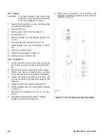
10-2.HORN REPLACEMENT
1.
Turn off the key switch and disconnect the batter-
ies.
2.
Remove the compartment covers as described in
paragraph
3.
Tag and disconnect all electrical connections from
horn.
4.
Remove screw, lock washer, flat washer and
horn.
5.
Install horn and secure with screw, lock washer,
flat washer.
6.
Install the compartment covers as described in
paragraph
7.
Reconnect the batteries and turn on the key-
switch.
Summary of Contents for CB33
Page 9: ...BL CB33 0115 03 01 2018 2 3 Figure 2 2 Sample of Operator Check List R6479...
Page 12: ...2 6 BL CB33 0115 03 01 2018 NOTES...
Page 18: ...3 6 BL CB33 0115 03 01 2018 NOTES...
Page 38: ...4 20 BL CB33 0115 03 01 2018 NOTES...
Page 44: ...5 6 BL CB33 0115 03 01 2018 NOTES...
Page 46: ...6 2 BL CB33 0115 03 01 2018 Figure 6 1 Drive Assembly DP_0004...
Page 48: ...7 2 BL CB33 0115 03 01 2018 Figure 7 1 Drive Assembly DP_0004...
Page 49: ...BL CB33 0115 03 01 2018 7 3 Figure 7 2 Load Wheels DP_0007...
Page 50: ...7 4 BL CB33 0115 03 01 2018 NOTES...
Page 52: ...8 2 BL CB33 0115 03 01 2018 Figure 8 2 Elevation System Telescopic DP_0008...
Page 54: ...8 4 BL CB33 0115 03 01 2018 Figure 8 3 Mast Three Stage Mast DP_0009...
Page 56: ...8 6 BL CB33 0115 03 01 2018 NOTES...
Page 58: ...9 2 BL CB33 0115 03 01 2018 Figure 9 1 Hydraulic System DP_0018...
Page 60: ...9 4 BL CB33 0115 03 01 2018 Figure 9 3 Elevation System Telescopic DP_0008...
Page 66: ...9 10 BL CB33 0115 03 01 2018 Figure 9 8 Secondary Lift Cylinder Three Stage Mast DP_0012...
Page 69: ...BL CB33 0115 03 01 2018 9 13 Figure 9 10 Tilt Cylinder DP_0016...
Page 70: ...9 14 BL CB33 0115 03 01 2018 NOTES...
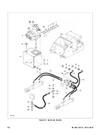
Page 72: ...10 2 BL CB33 0115 03 01 2018 Figure 10 1 Electrical System R6478 DP_0022...
Page 73: ...BL CB33 0115 03 01 2018 10 3 Figure 10 2 Electrical Panel R6478 DP_0023...
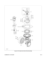
Page 75: ...BL CB33 0115 03 01 2018 10 5 Figure 10 3 Transmission Motor Brake Assembly DP_0004...
Page 76: ...10 6 BL CB33 0115 03 01 2018 NOTES...
Page 77: ...BL CB33 0115 03 01 2018 11 1 SECTION 11 OPTIONAL EQUIPMENT...
Page 78: ...11 2 BL CB33 0115 03 01 2018 NOTES...
Page 80: ...12 2 BL CB33 0115 03 01 2018 Figure 12 1 Steering System DP_0001...
Page 82: ...12 4 BL CB33 0115 03 01 2018 Figure 12 1 Steering System Continued DP_0001...
Page 84: ...12 6 BL CB33 0115 03 01 2018 Figure 12 2 Control Head DPP_0002...
Page 86: ...12 8 BL CB33 0115 03 01 2018 Figure 12 3 Control Head when Side Shift option DP_0035...
Page 88: ...12 10 BL CB33 0115 03 01 2018 Figure 12 4 Drive System DP_0003...
Page 90: ...12 12 BL CB33 0115 03 01 2018 Figure 12 5 Drive Assembly Used up to serial S2410419 DP_0004...
Page 94: ...12 16 BL CB33 0115 03 01 2018 Figure 12 7 Drive Assembly Used from serial 325130601 DP_0032...
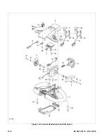
Page 104: ...12 26 BL CB33 0115 03 01 2018 Figure 12 10 Compartment DP_0005...
Page 106: ...12 28 BL CB33 0115 03 01 2018 Figure 12 11 Frame DP_0006...
Page 108: ...12 30 BL CB33 0115 03 01 2018 Figure 12 11 Frame Continued DP_0006...
Page 110: ...12 32 BL CB33 0115 03 01 2018 Figure 12 12 Load Wheels DP_0007...
Page 112: ...12 34 BL CB33 0115 03 01 2018 Figure 12 13 Elevation System Telescopic DP_0008...
Page 114: ...12 36 BL CB33 0115 03 01 2018 Figure 12 13 Elevation System Telescopic Continued DP_0008...
Page 116: ...12 38 BL CB33 0115 03 01 2018 Figure 12 14 Elevation System Three Stage Mast DP_0009...
Page 118: ...12 40 BL CB33 0115 03 01 2018 Figure 12 14 Elevation System Three Stage Mast Continued DP_0009...
Page 124: ...12 46 BL CB33 0115 03 01 2018 Figure 12 16 Lift Carriage Three Stage Mast DP_0014...
Page 126: ...12 48 BL CB33 0115 03 01 2018 Figure 12 17 Side Shift Assembly DP_0034...
Page 128: ...12 50 BL CB33 0115 03 01 2018 Figure 12 18 Chain Assembly DP_0017...
Page 134: ...12 56 BL CB33 0115 03 01 2018 Figure 12 21 Hydraulic System Used with Side Shift DP_0036...
Page 136: ...12 58 BL CB33 0115 03 01 2018 Figure 12 22 Tilt System DP_0015...
Page 138: ...12 60 BL CB33 0115 03 01 2018 Figure 12 23 Lift System Telescopic Not with Side Shift DP_0019...
Page 140: ...12 62 BL CB33 0115 03 01 2018 Figure 12 24 Lift System Telescopic With Side Shift DP_0037...
Page 146: ...12 68 BL CB33 0115 03 01 2018 Figure 12 26 Lift Cylinder Telescopic DP_0010...
Page 148: ...12 70 BL CB33 0115 03 01 2018 Figure 12 27 Free Lift Cylinder Three Stage Mast DP_0011...
Page 150: ...12 72 BL CB33 0115 03 01 2018 Figure 12 28 Secondary Lift Cylinder Three Stage Mast DP_0012...
Page 156: ...12 78 BL CB33 0115 03 01 2018 Figure 12 31 Pump and Motor Not when Side Shift DP_0021...
Page 158: ...12 80 BL CB33 0115 03 01 2018 Figure 12 32 Pump and Motor When Side Shift DP_0039...
Page 160: ...12 82 BL CB33 0115 03 01 2018 Figure 12 33 Electrical System ELECTRICAL SYSTEM DP_0022...
Page 162: ...12 84 BL CB33 0115 03 01 2018 Figure 12 34 Electrical Panel DP_0023...
Page 168: ...12 90 BL CB33 0115 03 01 2018 Figure 12 37 Wiring Cables DP_0025...
Page 170: ...Big Lift LLC...