52
•
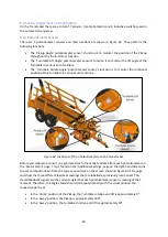
The ‘Fork
Safety Prox’ is
used to detect the position of the forks when they are at the rear of
the trailer.
•
The ‘Rear Pad Full’ sensor is to detect when the trailer is ‘full’ of bales and tells the t
railer to
either close up or perform the ‘Extra Layer’ function i
f it is
‘Active’.
•
The ‘Guidebar Full
i
n Prox’
detects when the Guidebar is fully retracted for
‘
Road Mode
’
and
stops the pickup being raised when the latch is engaged.
•
The ‘Bed Down, Table Retracted Prox’ detects when the turntable retracts in ‘Auto
-
Stack’
and
the
‘Auto Lower Turntable’ functions. In the ‘Auto Tip Bed Down Function’, i
t senses when the
platform is lowered on the Stops.
Figure 66: Location of Inductive Switches on Transtacker
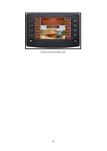
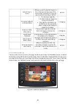
The status of the sensors is shown on
Figure 63. The 4 sensors all have
coloured dots next to them denoting their status. The possible statuses are explained below:
•
A red dot shows the sensor is healthy and the sensor is
‘not made’
•
A green dot
shows the sensor is healthy and the sensor is ‘made’
•
A blue dot shows there is an issue with either the sensor or with the wiring harness going
back to the ECU (see section 9.1.2 in troubleshooting section).
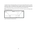
The meaning of ‘made’ and ‘not made’ depend
s on how close metal is to the sensor. The sensors have
a working range o
f 0 to 8mm. A sensor will be ‘made’ when there is metal within the 8mm tolerance
which will activate the sensor and
‘
not made
’
when the metal moves away beyond the 8mm
tolerance.
For visual clarification on whether the sensor is made, there is an LED built into the sensor near the
M12 connector. When the LED is orange, the sensor is ‘made’. If the sensor displays no LED light then
the sensor is ‘not made’. Overtime, the sensors may n
eed adjusting due to wear in the machine.
Summary of Contents for Transtacker
Page 7: ...7 3 0 Machine Overview Figure 1 Transtacker Overview...
Page 43: ...43 Figure 59 Auto Settings Screen...
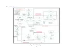
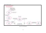
Page 57: ...57 8 1 Auto Pickup Sequence Figure 69 Auto Pickup Diagram...
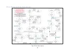
Page 58: ...58 8 2 Auto Stack Sequence both with and without tie Figure 70 Auto Stack Diagram...
Page 59: ...59 8 3 Auto Lower Turntable Figure 71 Auto Lower Turntable Diagram...
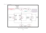
Page 60: ...60 8 4 Auto Open Sequence Figure 72 Auto Open Diagram...
Page 61: ...61 8 5 Auto Tip Bed Down Sequence Figure 73 Auto Tip Bed Down Diagram...
Page 62: ...62 8 6 Road Mode Sequence Figure 74 Road Mode Diagram...


