51
6.4.2 Calibration of Potentiometers
Turn the screen off and back on again so the main work screen is displayed. S
croll to ‘Additio
nal
Sett
ings’ and press ‘Calibrate Sensors’
. If you are unsure how to find
the ‘C
alibrat
e Sensors’ page,
see
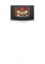
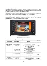
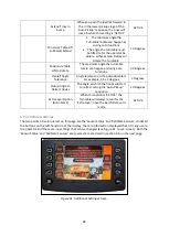
section 6.3. You will then have the screen displayed shown in Figure 65. You can then choose which
POT you wish to calibrate.
Figure 65: Calibrate Sensors Screen.
Once you’ve selected the sensor to calibrate, follow
ing the onscreen instructions, carry out the
following steps:
1.
Move the joystick forward or backwards as instructed until the Transtacker stops moving.
2.
Once the machine has stopped moving, press the button next to the floppy disc symbol (4
th
button down on right hand side of screen).
3.
P
ress the ‘
Menu
’ button and the
joystick directional arrow and the instructions will change.
4.
Move the joystick forward or backwards as instructed until the Transtacker stops moving.
o
NOTE
: The Transtacker should move in the opposite direction to step 1.
5.
Once the machine has stopped moving then press the button next to the floppy disc symbol
(4
th
button down on right hand side of screen).
6.
You can then exit this screen by pressing the ‘Enter’ button.
7.
If you wish to calibrate more than
one sensor, you can press the ‘Calibrate Sensors’ an
d repeat
from step 1.
8.
Once the calibration/s are complete, return to section to 6.4.1 and go to
‘
Sensor Status
’
to
verify the calibration procedure has been completed successfully.
NOTE
: If you want to calibrate the Turntable rotation sensor, the Turntable MUST be raised to
approximately 45 degrees before starting the calibration procedure. To raise the Turntable, go to
‘Stack Mode’, press the bottom right button and push the joystick forward.
6.4.3 Inductive Switches and adjustment
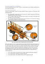
There are four inductive sensors located around the Transtacker that are used in auto functions. The
locations around the Transtacker are shown in Figure 66 and their names and functions are explained
below:
Summary of Contents for Transtacker
Page 7: ...7 3 0 Machine Overview Figure 1 Transtacker Overview...
Page 43: ...43 Figure 59 Auto Settings Screen...
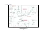
Page 57: ...57 8 1 Auto Pickup Sequence Figure 69 Auto Pickup Diagram...
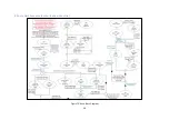
Page 58: ...58 8 2 Auto Stack Sequence both with and without tie Figure 70 Auto Stack Diagram...
Page 59: ...59 8 3 Auto Lower Turntable Figure 71 Auto Lower Turntable Diagram...
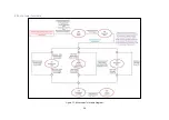
Page 60: ...60 8 4 Auto Open Sequence Figure 72 Auto Open Diagram...
Page 61: ...61 8 5 Auto Tip Bed Down Sequence Figure 73 Auto Tip Bed Down Diagram...
Page 62: ...62 8 6 Road Mode Sequence Figure 74 Road Mode Diagram...


