background image


11 

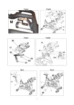
Position  it  correctly  and  then  tighten  knob  (2)  by 

turning  it  clockwise.  Attach  the  front  cover  (89)  on 

the body (A), use screw (86) to fix. 

Set  and  tighten  the  screw  (150)  to  guide  the 

handlebar  post,  then  place  cover  for  handlebar 

(63), screw it with screws (67). Fig.3D. 

Move  the  post  forward  to  the  farthest  position. 

Insert  the  support  (M)  below  the  monitor  support, 

Fig.3A. Insert the M8 screw through the post and fix 

the support (M). 


ADJUSTING THE HANDLEBAR 

HORIZONTALLY.- 

Position  the  handlebar  (20)  at  a  comfortable 

distance  for  doing  exercise,  now  tighten  knob  (17) 

securely, Fig.3B. 


ADJUSTING THE HANDLEBAR VERTICALLY.- 

Position  the  handlebar  (20)  at  a  comfortable 

distance  for  doing  exercise,  now  tighten  knob  (2) 

securely, Fig.3B. 

Stay  within  the  references  0-14  without  going 

beyond the “MIN INSERT” mark. 


FITTING THE ELECTRONIC MONITOR.- 

Get  the  cable  sticking  out  of  the  main  body  (100) 

through  the  plate  (101),  connect  the  terminal  into 

the terminal on the back of the monitor (62), Fig.3B, 

and secure it with the two screws. 

Important:  Make  sure  the  cable  position  is  correct. 

Incorrect  cable  connection  can  cause  permanent 

damage to the machine. 

Position  the  monitor  (62)  and  the  support  plate 

(101)  on  the  handlebar  support  (M)  and  screw  it 

with the screws (71). 


ATTACHING THE SADDLE.- 

Fit the saddle bracket (1), Fig.4, onto the horizontal 

saddle  tube  (38),  as  shown  in  Fig.4,  fit  the  saddle 

into  position  and  tighten  the  nuts  on  the  bracket 

securely.  

Next insert the horizontal saddle tube (38) through 

the  hole  on  the  saddle  post  (39),  Fig.4,  position  it 

correctly and tighten the knob (2), Fig.4.  

Insert  the  saddle  post  (39)  into  the  boss  on  the 

main  body  (A),  position  it  correctly  and  tighten  the 

saddle  post  by  using  the  adjustment  knob  (2A), 

Fig.4, turning it clockwise.  


ADJUSTING THE SADDLE HEIGHT.- 

Loosen  the  saddle  post  adjustment  knob  (2A) 

slightly  by  turning  it  anticlockwise,  Fig.4,  move  the 

saddle to a position comfortable for doing exercise 

and then tighten the adjustment knob (2A) securely 

by turning it clockwise. 

Stay  within  the  references  0-19  without  going 

beyond the “MIN INSERT” mark. 


HORIZONTAL ADJUSTMENT OF THE SADDLE.- 

Loosen  the  knob  (2)  slightly  by  turning  it 

anticlockwise, Fig.4, move  the saddle to a position 

comfortable for doing exercise and then tighten the 

knob (2) securely by turning it clockwise.  

FITTING THE PEDALS.- 

The  assembly  instructions  for  the  pedals  must  be 

followed  to  the  letter,  fitting  these  incorrectly  could 

damage  the  screw  thread  on  either  the  pedal  or  the 

crank. 

Right and left refer to the position that the user adopts 

when sitting on the saddle to do the exercises.  

The right-hand pedal (9R), marked with the letter (R), 

screws onto the right-hand crank, also marked with an 

(R), in a clockwise direction. Tighten securely, Fig.5. 

The  left-hand  pedal  (9L),  marked  with  the  letter  (L), 

screws onto the left-hand crank, also marked with an 

(L),  in  an  anti-clockwise  direction.  Tighten  securely, 

Fig.5. 


EXERTION SETTINGS.- 

For  regular  control  of  exercise  settings,  this 

appliance  is  equipped  with  a  tensioning  control 

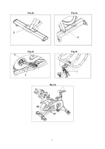
(22), located on the stem of the main body (A) Fig.6 

which,  when  lifted  in  the  direction  of  the  arrow, 

indicates the resistance settings of the appliance in 

the monitor. 

To  increase  the  pedalling  resistance,  lift  the 

tensioning  control  (22)  until  the  exertion  level  best 

suits your exercise requirements. 

To  decrease  the  pedalling  resistance,  lower  the 

tensioning control (22). 


Important: 

This  tensioning  control  (22)  has  an 

emergency  braking  system  which,  when  fully  lifted 

in  the  direction  of  the  arrow,  as  shown  in  Fig.6, 

causes a sudden braking force for the flywheel.  


LEVELLING.- 

Once the unit has been placed into its final position, 

make sure that it sits flat on the floor and that it  is 

level.  This  can  be  achieved  by  screwing  the 

adjustable feet (10) up or down, as shown in Fig.6. 


MOVEMENT & STORAGE.- 

The  unit  is  equipped  with  wheels  (13)  Fig.6,  to 

make it easier to move. The  wheels  located at the 

front  of  your  unit  make  it  easier  to  move  it  into  a 

chosen  position,  by  lifting  the  rear  of  the  unit  up 

slightly  and  pushing  it,  as  shown  in  Fig.7.  Store 

your  unit  in  a  dry  place,  preferably  not  subject  to 

changes in temperature. 


ACCESS TO BATTERIES.- 

This  model  has  3  AAA  rechargeable  batteries  that 

allow  to  display  the  information  for  a  few  seconds 

after  the  user  finishes  the  exercise.  To  access  the 

battery  box,  remove  the  two  screws  (57)  and  then 

remove the cover (59), Fig. 16. 


OPERATIONS BEFORE BEGINNING 

1.- Check that all components are properly installed: 

The nuts of the stands must be tightened with a torque 

of 20 Nm. 

The  pedals  must  have  been  sealed  with  Loctite  242 

and  tightened  with  the  appropriate  torque  (a  46  Nm 

torque must be applied). 

Summary of Contents for H945ANT

Page 1: ...H945ANT Instrucciones de montaje y utilización Instructions for assembly and use Instructions de montage et utilisation Montage und Gebrauchsanleitung ...

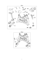
Page 2: ...2 Fig 1 Fig 2 ...

Page 3: ...3 Fig 3A Fig 3B Fig 3C Fig 3D Fig 4 Fig 5 ...

Page 4: ...4 Fig 6 Fig 7 Fig 8 Fig 9 Fig 10 Fig 11 ...

Page 5: ...5 Fig 12 Fig 13 Fig 14 Fig 15 Fig 16 ...

Page 6: ...funciona correctamente Precaución Antes de comenzar a utilizar la bicicleta consulte a su médico Esta advertencia es especialmente importante para personas de edades superiores a 35 años o con problemas de salud Guarde estas instrucciones INDICACIONES GENERALES 1 Esta unidad ha sido diseñada para uso profesional El peso de usuario no debe exceder de 150Kg 2 Los padres y personas responsables de lo...

Page 7: ...nitor 62 y la chapa de soporte 101 sobre el soporte manillar M y atorníllelo con los tornillos 71 MONTAJE DEL SILLÍN Introduzca la abrazadera del sillín 1 Fig 4 en el tubo horizontal de la tija 38 como muestra la Fig 4 Coloque el sillín en posición y apriete las tuercas de la abrazadera fuertemente Seguidamente introduzca el tubo horizontal de la tija 38 por el agujero del tubo de tija 39 Fig 4 Po...

Page 8: ...as tija de manillar y superficie horizontal del amarre de tija manillar Fig 15 Modo de aplicación Agitar bien antes de usar Aplicar a una distancia de entre 20 y 30 cm de la superficie a tratar utilizando el tubo de extensión Esperar dos minutos hasta que estabilize el producto Extender con un paño cuidadosamente el producto dejando una capa uniforme sobre la superficie a tratar y retirar el sobra...

Page 9: ...xido Aplicar el BH indoor cycling protector con un paño limpio y seco Secar una vez aplicado 4 Los 3 pomos de apriete que dispone la unidad se deberán aflojar y rociar con el spray de engrase Wurth con el objeto de garantizar la movilidad de los mismos Anualmente 1 Limpiar con el jabón NXTde MEGUIAR S echando jabón en un cazo con agua Agitar para generar espuma Aplicar con una esponja húmeda y sec...

Page 10: ...e into account and how this can often lead to hazardous situations and behaviour resulting in accidents Under no circumstances should this appliance be used as a toy 3 The owner is responsible for ensuring that anyone who uses the machine is duly informed about the necessary precautions ASSEMBLY INSTRUCTIONS The assistance of a second person is recommended when assembling this unit WARNING The rep...

Page 11: ...se and then tighten the knob 2 securely by turning it clockwise FITTING THE PEDALS The assembly instructions for the pedals must be followed to the letter fitting these incorrectly could damage the screw thread on either the pedal or the crank Right and left refer to the position that the user adopts when sitting on the saddle to do the exercises The right hand pedal 9R marked with the letter R sc...

Page 12: ...k that the apparatus is safe and appropriate for exercise 2 A cloth or towel should be used to remove sweat after the session has ended Weekly for the first month 1 Check the tightness of the pedal and crank with a torque wrench The tightening torque must be 46 Nm Weekly 1 Thoroughly inspect each apparatus to make sure it is in safe and proper working order Check screws nuts and bolts pedal cages ...

Page 13: ...ce Incorrect assembly by the purchaser Failure to follow the assembly instructions as stated in the manual provided Damage caused by the cleats of the shoes Stretching exercises should be performed in a suitable place and never on the machine Do not hesitate to get touch with the Technical Assistance Service if you have any queries by phoning customer services see last page in manual BH RESERVES T...

Page 14: ...r doit faire des échauffements par l intermédiaire d exercices d étirement 11 Ne pas utiliser le vélo s il fonctionne incorrectement Précaution Consultez votre médecin avant d entreprendre des exercices sur cette machine Cette remarque s adresse plus particulièrement aux personnes âgées de de 35 ans et aux personnes qui ont des problèmes de santé Conservez cette notice CONSIGNES GÉNÉRALES 1 Cette ...

Page 15: ... des damages permanents à la machine Placez le moniteur 62 et la tôle de support 101 sur le support de guidon M9 et vissez le avec les vis 71 MONTAGE DE LA SELLE Introduire le collier de la selle 1 Fig 4 dans le tube horizontal de la tige 38 comme indiqué dans la Fig 4 placez la selle à la hauteur requise et vissez très fort les écrous du collier Introduire ensuite le tube horizontal de la tige 38...

Page 16: ...u guidon et surface horizontale d attache de la tige du guidon Fig 15 Mode d application Bien agiter avant l emploi Appliquer à une distance de 20 à 30 cm de la surface à traiter en utilisant le tube d extension Attendre deux minutes jusqu à ce que le produit se stabilise Étaler délicatement le produit à l aide d un chiffon en laissant une couche uniforme sur la surface à traiter et retirer l excè...

Page 17: ... rouille Appliquez le BH indoor cycling protector à l aide d un chiffon propre et sec Une fois appliqué sécher 4 Les 3 boutons de serrage dont dispose l unité devront être desserrés et vaporisés avec le spray de graissage Wurth dans le but de garantir leur mobilité Annuellement 1 Nettoyer avec le savon NXT de MEGUIAR S en mélangeant dans un récipient le savon avec de l eau Agiter pour faire mousse...

Page 18: ...en konsultieren Sie bitte Ihren Arzt Dieser Hinweis ist besonders wichtig für Personen die alter als 35 sind oder gesundheitliche Probleme haben Bevor Sie irgendein Trainingsgerät benutzen lesen Sie bitte stets die gesamten Anleitungen Bewahren Sie diese Anleitungen gut auf ALLGEMEINE HINWEISE 1 Dieses Gerät ist für den professionellen Gebrauch vorgesehen Das Gewicht des Benutzers darf 150 kg nich...

Page 19: ...t den zwei Schrauben fest Wichtig Stellen Sie sicher dass die Position des Kabels die richtige ist Ein falscher Anschluss kann einen dauerhaften Schaden am Gerät verursachen Plazieren Sie den Monitor 62 und das Halterungsblech 101 über den Lenker M und schrauben Sie es mit den Schrauben 71 fest MONTAGE DES SATTELS Setzen Sie die Sattelklemme 1 Fig 4 auf die Querstange des Sattels 38 Fig 4 Bringen ...

Page 20: ...uelstange Fig 14 6 Verbindung Pleuelstange mit Mittelteil Fig 14 7 Verchromte Flächen des Lenkerrohrs und horizontale Fläche der Lenkerrohrbefestigung Fig 15 Gebrauchsanweisung Vor Gebrauch gut schütteln Anwendung aus einer Entfernung von 20 bis 30 cm Abstand von der zu behandelnden Oberfläche unter Verwendung des Verlängerungsröhrchens Zwei Minuten warten bis sich das Produkt stabilisiert hat Das...

Page 21: ...forderlich den gesamten Heimtrainer zu wachsen jedoch sind die Teile die mit Schweiß in Berührung kommen besonders anfällig für Korrosion und sollten deshalb gut gewachst werden Den BH indoor cycling protector mit einem trockenen und sauberen Tuch auf das Gerät auftragen Nach der Anwendung trocknen 4 Die drei Feststellknöpfe des Geräts müssen gelockert und mit dem Wurth Fettspray besprüht werden u...

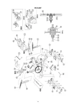
Page 22: ...22 H945ANT ...

Page 23: ...23 H945ANT ...

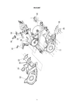
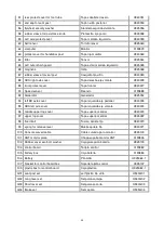
Page 24: ...allete trasero H940011 12 foot end cap Tapón caballete H940012 13 PU wheel Rueda transporte H925013 14 front foot tube complete Caballete delantero H940014 19 front protect cover for foot tube Tapa caballete delantero H940019 20 handlebar only Manillar H945020 21 handlebar post Tija manillar H940021A 22 resistance knob complete set Set pomo resistencia H945022 23 handlebar slider Deslizadera de ma...

Page 25: ...190888 92 Generator Generador H925052 94 left BB axle cover Tapa izquierda eje pedalier H940076 95 ABS left axle cover Tapa izquierda eje volante H940074 96 middle upper top cover Tapa superior central H940073 97 upper top cover Tapa superior central H945097 98 fixed bolt Tuerca apriete tija H940070 99 spring for release lever Muelle apriete tija H940071 100 Console curved cable Cable curvado para...

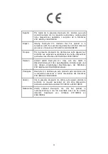
Page 26: ...65 CE et 2004 108 CE Deutsch Hiermit erklärt Exercycle S L dass sich das Gerät in Übereinstimmung mit den grundlegenden Anforderungen und den übrigen einschlägigen Bestimmungen der Richtlinien 2011 65 EG und 2004 108 EG befindet Português Exercycle S L declara que este producto está conforme com os requisitos essenciais e outras disposições das Directivas 2011 65 CE e 2004 108 CE Italiano Con la p...

Page 27: ... CHINA BH China Co Ltd Block A NO 68 Branch Lane 455 Lane 822 Zhen Nan RD Li Zi Yuan Putuo Shanghai 200331 P R C Tel 86 021 5284 6694 Fax 86 021 5284 6814 e mail info i bh cn BH HIPOWER UK Tel 44 2037347554 e mail sales uk bhfitness com AFTER SALES UK Tel 44 2074425525 e mail service uk bhfitness com BH HIPOWER FRANCE SAV FRANCE Tel 33 0 559423419 Fax 33 0810 000 290 savfrance bhfitness com BH Ger...

Reviews: