
3
75
E
N
G
IN
E ASS
E
M
B
LY AN
D CO
NTRO
LS
2
1
3
4
10Nm
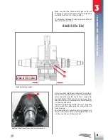
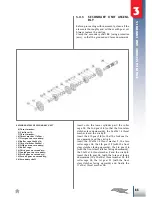
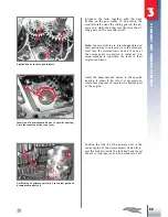
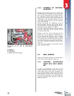
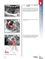
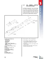
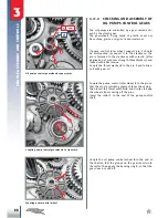
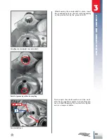
POSITIONING OF STOP CAM ON DESMODROMIC
DEVICE
1) Stop lever;
2) Stop cam;
3) Screw M6x30;
4) Movable pawl return spring.
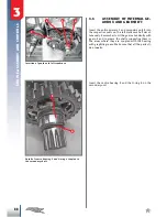
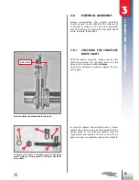
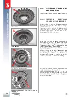
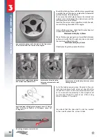
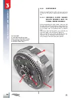
3.8.2 ASSEMBLY OF EXTERNAL
GEARSHIFT
Keeping the stop lever moved
1
in such a way
that the spring is compressed, position the stop
cam
2
on the protruding end of the desmodro
-
mic gearshift (external right crankcase). The
stop cam has only one correct position which is
determined by the particular shape of the end
of the desmodromic device and of the bottom
part of the stop cam.
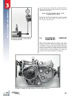
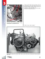
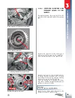
Proceed mounting the tightening screw
3
M6x30 between the stop cam and the desmo
-
dromic gearshift, after having applied medium-
resistance sealant: tighten it at 10Nm.
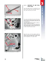
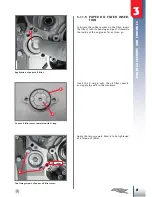
Insert the drive shaft together with the washer
in its seat keeping the return spring
4
of the
movable pawl pressed.
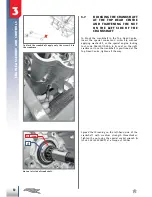
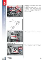
Wishing to test the correct functioning of the
entire unit, you just need to temporarily cou
-
ple the external gearshift lever and to simula
-
te the operation of changing gears, by lifting
and lowering the gearshift lever and having the
mainshaft of the gear unit rotate. The whole de
-
vice works properly if abnormal jamming does
not occur.
If the unit runs without oil, the device makes
more noise than usual.
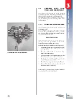
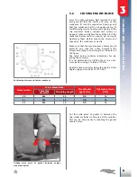
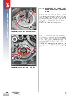
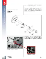
3.9
KICK StARtER
Before coupling the kickstarter to the crankcase
half, some controls must be carried out.
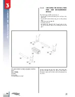
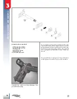
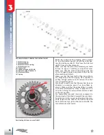
3.9.1 CHECKING KICKSTARTER
SHAFT UNIT AND ASSEM-
BLY
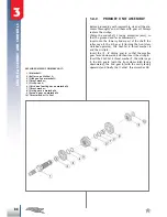
In order to disassemble all the parts of the
kickstart shaft, pull off the washer
11
at the end
of the shaft (on the side of the spring
16
), the
spring
16
, the kickstart sleeve
14
, and the lever
return spring
8
, which to be unfastened from
the shaft must be pulled in the radial direction
so that it is extracted from its hole. Pull out the
kickstart spacer
9
.