


3
118
E
N
G
IN
E ASS
E
M
B
LY AN
D CO
NTRO
LS
A
3
2
1
4
B
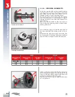
17Nm
10Nm
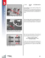
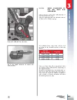
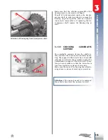
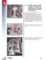
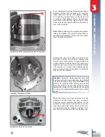
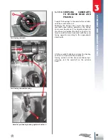
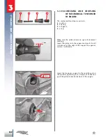
3.17.10 CYLINDER HEAD: REPOSI-
TIONING CALIBRATED DISCS,
ASSEMBLY OF FINGER FOL-
LOWER SHAFTS AND FINGER
FOLLOWERS AND COUPLING
THE SPARK PLUG
Clamp the cylinder head using protective jaws, grip
-
ping it at the head connection
A
.
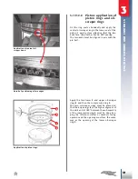
Put the calibrated discs
1
back in place in their original
positions (if not deteriorated see par. 3.17.3.3).
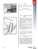
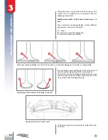
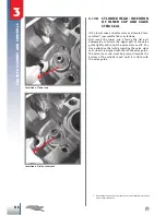
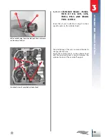
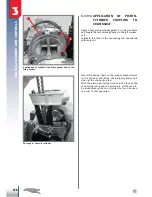
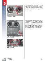
Insert the finger follower shaft
2
partly in the specific
seat as much as needed to be able to insert the ou
-
termost finger follower into the cylinder head first
3
.
Having fastened the outermost finger follower to the
shaft, push the shaft further until it reaches the seat
of the innermost finger follower. Having coupled the
innermost finger follower to the shaft push it all the
way into the cylinder head.
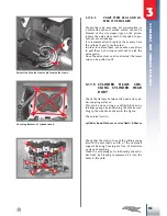
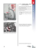
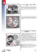
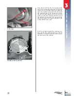
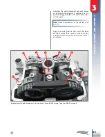
Couple the two caps
4
with the O-rings to the cylin
-
der head. They must be tightened at a torque of
10Nm.
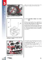
Apply the spark plug on the special wrench
B
(code
020440100 000)
, introduce the unit in the specific
housing and tighten at a torque of 17Nm.
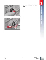
Insertion of shaft 1 on outermost finger follower 2.
Application of two finger follower shaft caps.