-22-
UG-TQ22-EN (V2.2-211226)
TQ-22
Mixer Reference
manual
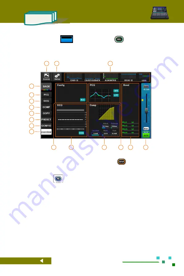
2.2.2 Overview of output channels
Click the channel label
or click the channel button
, the mixer will
automatically enter the output channel overview page, where you can browse most of the parameter
settings of the current channel. The physical knobs and buttons on the machine panel can be used to
quickly adjust the related parameter. There are 5 overview areas:
[Config], [PEQ], [GEQ], [Comp.], [Route
Assignment],
click the first 4 areas to enter the full screen mode of the corresponding function.
01
In the navigation bar, click the index page or the
fader page button to switch to the page where the
channel is located. The small bright spot in the
figure is the gain position indication of the channel.
02
System setup button, click to enter the system
parameter control page. Same function as the
button
on the panel.
03
Scene button, click to enter scene control page, save
or load the scene parameters you need. It has the
same function as the
button on the panel.
04
Home button, click to return to the channel home
page.
06
Click to switch to the GEQ control page.
05
Click to switch to the PEQ control page.
08
Click to switch to the [copy to] control page.
07
Click to switch to the compressor control page.
10
Click to switch to the channel configuration
page.
09
Click to switch to the parameter preset page.
11
Click to switch to the channel overview page.
12
The configuration overview area only displays but cannot be operated on the screen. Click to enter full screen mode.
13
The GEQ overview area, which only displays and cannot be operated on the screen. Click to enter full screen mode.
14
Compressor overview area, only display cannot be operated on screen. Click to enter full screen mode.
15
PEQ overview area, only display can not be operated on screen. Click to enter full screen mode.
16
The route sending overview area is only displayed, and cannot be operated on the screen. The progress bar indicates
the amount of transmission, and red indicates that the transmission is muted. The green text indicates the bus
corresponding to the current send knob.
17
Current channel master control board, adjustable gain and mute.
03
02
01
04
06
07
08
09
11
10
17
05
14
15
12
16
13


