


UG-TQ22-EN (V2.2-211226)
- 11-
TQ-22
Mixer Reference
manua
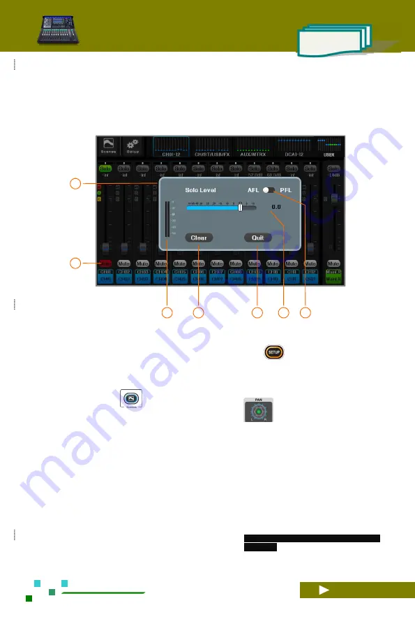
2.1. Input Channels
2.1.1 Home of input channels
01
In the navigation bar, click the corresponding index
page or the fader page button on the panel to
quickly switch to the page where the channel is
located. The small bright spot in the figure is the
channel gain position indication of the channel.
02
System setup button, click to enter the system
parameter control page. Same function as the
button
on the panel.
03
Scene button, click to enter scene control page, save
or load the scene parameters you need. It has the
same function as the
button on the panel.
04
This channel is assigned to the pan of the Main
L
/
R. Adjust it in the channel settings, or click the
screen to select the channel, and then adjust the
knob on the panel.
05
SOLO monitor switch.
06
Channel gain. Changed by fader adjustment.
07
Channel linking indicator. This indicator lights up
when two adjacent channels are linked.
08
The phantom power indicator lights up to
indicate that the + 48V output is valid.
09
Noise gate indicator, when lit, indicates that the
noise gate is valid.
10
Compressor indicator, lit to indicate that the
compressor is valid.
11
Channel gain fader.
12
Channel gain scale, unit: dB.
13
Channel mute switch, mute when lit.
14
The channel label contains the physical channel
numbers CH01, CH02, etc, as well as
user-definable
channel
names,
such
as
"MIC-01", "Guitar-02", and so on.
Click the channel label to enter the channel
edit menu
.
15
Channel preview area. Click the screen to select a
channel as the current channel, and rotate the main
knob to adjust its parameters.
16
Main L / R channel master control board with
adjustable gain and mute.
02
01
03
04
05
06
07


