BestCode Next 8 Series Technical Manual Download Page 105

BestCode Next Series 8 Technical Manual 

October 2022 


Page 91 of 290 


6.


Remove the Solvent Filter and 
discard in accordance with local 
regulations. 
 

7.


Install new Solvent Filter. 


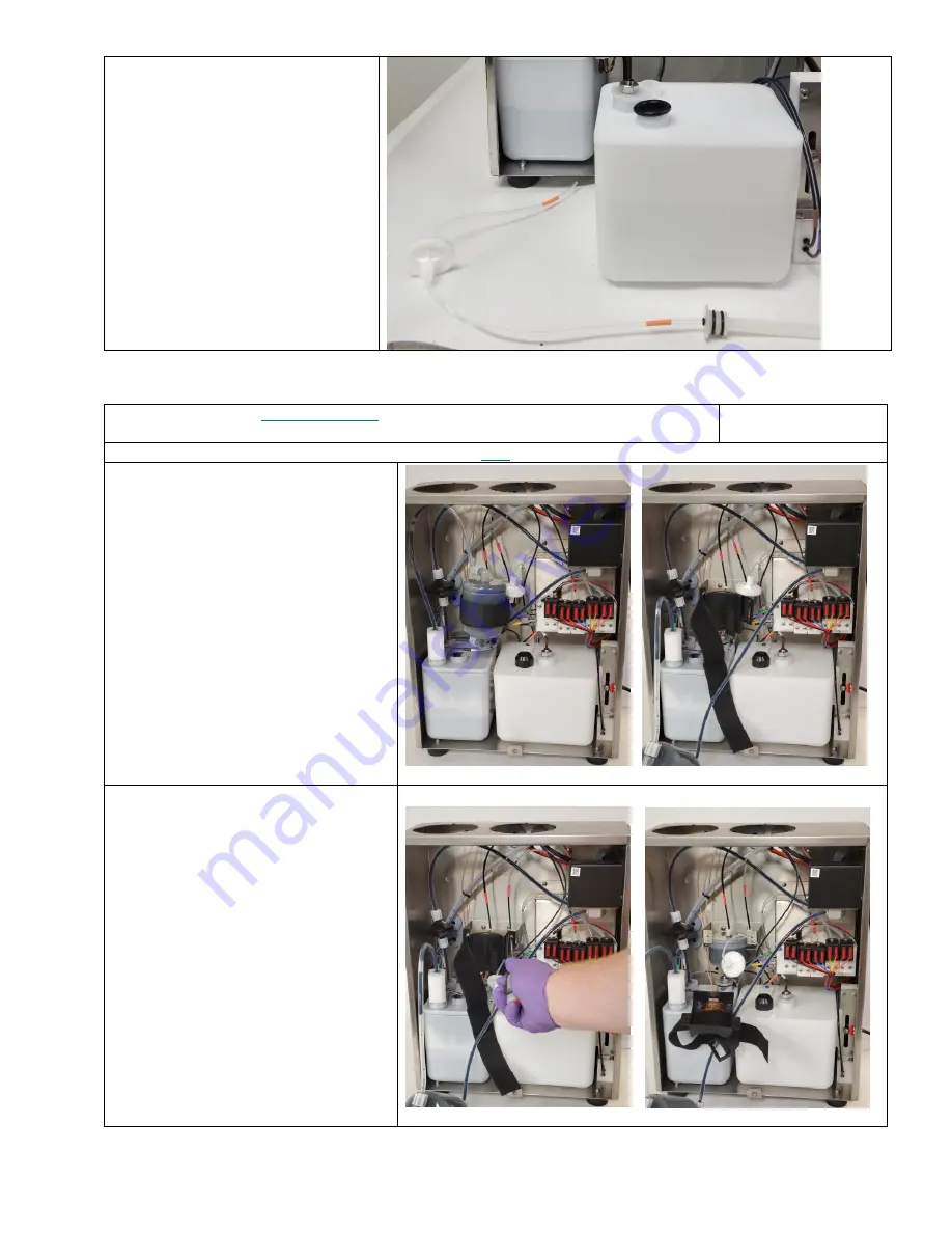
Dampener Printhead Assembly (31-0054-01) Replacement 

Be familiar with prope

safety information

 for handling fluids. 

Procedure Time: 15 
minutes


1.


Remove the Ink & Makeup SmartFill cup Instruction

here


2.


Remove the Main Ink Filter from the 
Filter Housing 


3.


Remove the SmartFilter Housing by 
removed the 2 M4 screws from the 
SmartFilter bracket 


4.


Locate the Dampener Printhead 
Assembly (31-0054-01) 


Summary of Contents for Next 8 Series

Page 1: ...cter printing systems Series 8 Continuous Ink Jet Printers print high speed reliable lot date sell by date and other identifying marks and codes on a wide range of substrates including plastic glass paper and more Version 01 06 00 October 2022 ...

Page 2: ......

Page 3: ......

Page 4: ......

Page 5: ...hether through an agent or otherwise the participation of another institution or person without the prior approval of BestCode A recipient may not reproduce disseminate copy disclose modify distribute and or publish this material without the written consent of BestCode This manual is available for download on the BestCode Portal BestCode Information 3034 SE Loop 820 Phone 1 817 349 8555 For produc...

Page 6: ... 2 2014 EN 61000 3 3 2013 Bureau of Indian Standards IS 13252 Part 1 2010 A1 2013 A2 2015 IEC 60950 1 2005 A1 2009 A2 2013 EurAsEC Customs Union TR CU 004 2011 on safety of low voltage equipment TR CU 020 2011 on the electromagnetic compatibility of technical devices BestCode Next Series 8 Printer is REACH complaint BestCode Next Series 8 Printer is RoHS compliant as it pertains to 2011 65 EU Best...

Page 7: ...components This manual contains several links to Youtube videos on proper maintenance and operation of the BestCode CIJ Printers They are throughout the document and should be reviewed The entire library of support videos can be found here and they serve as an excellent supplement to this manual https support bestcode co training videos Distributors may contact info bestcode co for Technician Leve...

Page 8: ...SE DOORS FORM THE FIRE BARRIER THAT PREVENTS FLAMES FROM EXITING THE DEVICE WARNING EQUIPMENT DAMAGE Connect the pump fittings before powering on the machine for the 1st time Failure to follow this instruction will cause permanent damage to the pump Electrical Safety Information This section contains information for proper electrical safety practices Earth Grounding BestCode Series 8 printers are ...

Page 9: ...ust be Grounded Earthed Failure to provide adequate grounding earthing will result in damage to the circuit board printhead and the power supply This damage will occur over time The Next Series 8 CIJ Power Supply generates a DC Ground to support the function of the Printer but this does not protect from static or power surges Supply Power WARNING PERSONAL INJURY EQUIPMENT DAMAGE When connected to ...

Page 10: ...cables sockets and power supply module for signs of wear damage and corrosion Inspect all ground connections for corrosion ink build up or any other contaminant that would impede the ability to provide earth ground to the Printer Damaged or poorly connected cables can cause damage to the Printer and may also cause serious injury or death Fluidic Safety Guidelines WARNING PERSONAL INJURY THE SAFETY...

Page 11: ...hout being prompted by the system Over filling the Printer can cause leaks and damage WARNING EQUIPMENT DAMAGE The printhead should never be submerged in Cleaner This can cause un repairable damage to the printhead The printhead must be dry before starting the Printer WARNING PERSONAL INJURY EQUIPMENT DAMAGE Ink and Makeup produce vapor that is high flammable Ensure that adequate ventilation is pr...

Page 12: ...0 Printhead Selection 10 SYSTEM SETUP 11 CONTROLLER MOUNTING 11 PRINTHEAD MOUNTING 13 PRE POWER UP GUIDE 15 COMMISSIONING 17 Pre fluid test 17 Commission the Ink Type 17 Adding Fluids 18 First time jet Start 19 Verify the Modulation 20 BASIC OPERATIONS 21 POWER ON OFF 21 START STOP JET 21 SELECTING A MESSAGE FOR PRINT 22 NAVIGATING THE NEXT SERIES 8 USER INTERFACE 23 HOME SCREEN FEATURES 23 MESSAG...

Page 13: ... Manifold Replacement 109 Ink Valve Replacement 111 Ink Valve Cleaning 112 Replacing the Ink Tank 114 Flushing the Ink System 115 ELECTRONIC SERVICE ROUTINES 116 Main CPU Board Replacement 116 Display Replacement 122 Integrating External Peripheral devices 125 PRINTHEAD SERVICE ROUTINES 131 Nozzle Replacement 131 Jet Alignment 133 Drop Generator Replacement 135 Modulation Calibration 138 Gutter Re...

Page 14: ...B 214 Multiple Version Per Stick 216 FIRMWARE LOADING PROCESS 216 Firmware Load Troubleshooting 218 BCTOOLS 230 REMOTE COMMUNICATION 242 General Overview 242 APPENDIX 243 APPENDIX A COMPLIANCE CERTIFICATES 244 APPENDIX B FLUID RANGE FW VERSION 01 06 00 07 246 APPENDIX C SYSTEM STANDS BRACKETS AND PERIPHERAL DIAGRAMS 249 APPENDIX D SPECIFIC FUNCTION TESTING 255 APPENDIX E PRINT APPLICATIONS SETUP 2...

Page 15: ...uto programmed codes Characters per message 3000 characters 100 per field maximum Maximum Message Length 16000 Rasters or 320 inches 8 1m 50 DPI Screen 10 4 LCD with Touch Screen Interface RS232 Ethernet Enclosure IP 65 304 Stainless Steel Air Filter EN 779 F5 Class Filter 50 0 3micron 100 10 micron Peripheral Photocell 1 Shaft Encoder Alarm Beacon Photocell 1 Photocell 2 Shaft Encoder 4 Stage Ala...

Page 16: ...1 Electronic Service Door 25 0003 08 2 LCD 10 4 Touch Assembly 20 5014 01 3 Air Filter Service Entry Door 4 Peripheral bulkhead knockouts Misc 5 Power cord grommet 6 Product Identification Label 7 Fluidic Service Door 25 0004 06 8 Makeup Fill cap 27 0005 04W 9 Ink Fill cap 27 0005 04B This part is non replaceable Varies by cord set Height 19 4 493mm Width 15 4 392mm Depth 12 5 318mm Dry Weight 45 ...

Page 17: ...Ink SmartFilter See Here 3 Venturi 20 5032 01 Varies by Generation and model 4 Ink Tank 20 0012 01 5 SmartFill Makeup Cup 20 0025 01 6 Ink Pump 32 0001 01 or 32 5005 01 for Standard Systems 32 0015 01 for Opaque 7 Valve Manifold Assembly 20 0040 01 Varies by Generation 8 Viscometer Assembly 20 0015 01 9 Makeup Tank 20 0013 01 1 2 3 4 5 6 7 8 9 ...

Page 18: ...2 0038 04 9 Phase Detector 3 Printhead Thumb Screw 28 0047 01 10 Negative High Voltage Plate 4 Printhead Front Cover 22 0039 04 11 Positive High Voltage Plate 5 Gutter Detect 22 0083 01 12 Gutter Series 8 22 0010 13 6 Cam Series 8 PH 22 0003 05 13 Print slot 7 Drop Generator Varies by model see pricelist This part is non replaceable Length 9 227 7mm Height 1 5 38 1mm Width 1 5 38 1mm Umbilical Len...

Page 19: ...BestCode Next Series 8 Technical Manual October 2022 Page 5 of 290 90 Printhead Length 7 47 189 7mm Width 6 29 159 7mm Height 1 5 38 1mm Umbilical Length 9 10 3m Available in 15ft 4 5m ...

Page 20: ...asters Second 1269 9 1269 9 2080 5 2080 5 2079 0 2432 4 2773 8 2838 3 Characters Second 634 9 634 9 1040 3 1040 3 1039 5 1216 2 577 9 1419 2 Feet Minute 3 23 3 23 5 28 5 28 5 28 6 18 2 94 7 21 Meters Second 7 7 4 5471 5471 9376 9376 9404 11044 12590 12866 Rasters Second 1367 8 1367 8 2344 0 2344 0 2350 9 2761 0 3147 5 3216 4 Characters Second 7 5 1094 2 1094 2 1875 2 1875 2 1880 7 2208 8 2518 0 25...

Page 21: ... 1 547 1 937 6 937 6 940 4 1104 4 524 6 1286 6 Feet Minute 2 78 2 78 4 76 4 76 4 78 5 61 2 66 6 54 Meters Second 9 9 7 3581 3581 5332 5332 5681 6758 7754 7826 Rasters Second 511 6 511 6 761 7 761 7 811 5 965 5 1107 8 1117 9 Characters Second 358 1 358 1 533 2 533 2 568 1 675 8 323 1 782 6 Feet Minute 1 82 1 82 2 71 2 71 2 89 3 43 1 64 3 98 Meters Second 12 12 8 2693 2693 4072 4072 4506 5328 6122 6...

Page 22: ...ters Second 7 5 445 6 445 6 678 8 678 8 801 5 1012 3 1148 1 1105 8 Characters Second 222 8 222 8 339 4 339 4 400 8 506 1 239 2 552 9 Feet Minute 1 13 1 13 1 72 1 72 2 04 2 57 1 22 2 81 Meters Second 2L9 9 7 1279 1279 1687 1687 2073 2642 2883 N A Rasters Second 182 8 182 8 241 0 241 0 296 2 377 4 411 8 Characters Second 127 9 127 9 168 7 168 7 207 3 264 2 120 1 Feet Minute 0 65 0 65 0 86 0 86 1 05 ...

Page 23: ...1 124 9 56 7 Feet Minute 0 29 0 31 0 31 0 50 0 63 0 29 Meters Second 4L7 7 4 N A 1081 1543 1961 2137 Rasters Second 270 2 385 6 490 3 534 2 Characters Second 7 5 216 2 308 5 392 3 427 3 Characters Second 108 1 154 3 196 1 89 0 Feet Minute 0 55 0 78 1 00 0 45 Meters Second 5L5 5 5 765 1085 1381 1504 Rasters Second 152 9 217 0 276 3 300 8 Characters Second 76 5 108 5 138 1 62 7 Feet Minute 0 39 0 55...

Page 24: ...t Includes air drier attached to system See here POSAIR Add on air pump for prevent dust dirt or water build up in the printhead See here Printhead Selection Printhead Environment Model Condition 81 82 86 87 88 88SS 88FG 88SOP 88SHS 88SHS1 88SHSOP 88SOPHS1 88SM Limited space Add 90DPH Add 90DPH Add 90DPH X Printing on bottom of product Add 90DPH Add 90DPH Add 90DPH X Character height less than 0 0...

Page 25: ...rophic damage to the electronic components Never print into an ungrounded container This may cause serious injury or death to the operator and will also cause catastrophic damage to the electronic components Some fluids are flammable electrical shocks are a serious fire hazard WARNING PERSONAL INJURY EQUIPMENT DAMAGE The resistance between equipment Cabinet or Printhead and the factory earth groun...

Page 26: ...n Failure to observe these warnings may result in severe injury or death WARNING PERSONAL INJURY EQUIPMENT DAMAGE Make sure that the Supply Power is within the acceptable ranges for operating the Printer These ranges are clearly marked on the side of the Printer 100 240Vac 240V 50hz 22 5V Amps 225 watts 50 60Hz 120V 60hz 45V Amps 45 watts 3A MAX Ideal Controller Mounting Setup Time 30 minutes 1 Fo...

Page 27: ...rinthead This will permanently damage the main board WARNING PERSONAL INJURY EQUIPMENT DAMAGE Most Inks and Makeups are highly flammable liquid Dried ink can also be highly flammable so great care should be taken to avoid exposing the fluid to heat sparks static and any other potential source of spark Inks and Makeups are potentially hazardous substances Always read the SDS of the Ink Makeup and C...

Page 28: ...amp is included with Kit 40 0003 01 Printhead Floor Mount Kit 40 0004 01 Printhead Conveyor Mount 2 The gutter should always be towards the floor 3 Keep the gap between the product and the print slot at 1 16 1 2 inch 4 Keep printhead square to the product to prevent print distortion A 5 10 angle between head and product may be necessary in high static environments ...

Page 29: ...e red tube is on the pressure side of the pump and flows into the main ink filter Verify the tube connects directly to the main BestCode Ink Filter 3 Remove the Black cap from the tube 4 Wet the pump fitting o ring with cleaner and firmly press the black tube into the rear fitting on the pump Pull back on the tube to ensure that it is completed seated and sealed into the pump fitting Failure to fu...

Page 30: ...Series 8 Technical Manual October 2022 Page 16 of 290 6 Remove the Nozzle Shipping Gasket The gasket is highly elastic and should be stretched outwards and then lifted up from between the nozzle and charge electrode ...

Page 31: ...is completed Pre fluid test Procedure Time 5 Minutes 1 Navigate to the fluidic screen Home Service Fluidic 2 Press each valve button one at a time and listen for the click Note Valve 1 Printhead will click when activated and de activated since it is a 3 way Listen for a Click Clack when cycling the valve on and off Valve Troubleshooting Here Commission the Ink Type Procedure Time 5 minutes 1 Navig...

Page 32: ...e Screen Leave the Ink Cap on 2 After the Success prompt remove the cap and press the bottle firmly into the Ink Smartfill Cup 3 Press OK after the bottle has completely drained 4 Place 1 un opened bottle of Makeup in the Makeup Smartfill Cup then press the Makeup Level button on the Home Screen Leave the Ink Cap on 5 After the Success prompt remove the cap and press the bottle firmly into the Mak...

Page 33: ...the printhead into the Printhead Clean Station 40 002 01 2 Disable the High Voltage and Phase 3 Press the Start Button on the Service Screen 4 Clear any errors that appear and repeat from Step 3 until the jet starts without errors 5 Stop the Jet then perform the backflush nozzle routine up to 6 times 6 Dry the printhead then start the Jet normally with Errors High Voltage and Phase enabled ...

Page 34: ...alibration label inside the Air Service Entry Door Note These values are generated by testing the machine at 20C controlled environment Different temperatures and ink types will vary the modulation set point 3 Decrease modulation to 30V below the set point and test the print 4 Increase the modulation to 30V above the set point and test the print a If the print is not acceptable perform a modulatio...

Page 35: ...dding too much makeup When the operator is logged in using the Technician Level Password all Starts Stops from the Home screen will be clean stops This is to help diagnose Clean Start and Clean Stop problems Quick Quick Start Quick Stop are technician tools to quickly start and stop the jet They do no utilize makeup in the start so they will not start or stop as clean as the Clean Start or Stop Th...

Page 36: ...Selecting a message for print 1 Press the Messages Button 2 Select the desire message 3 Press the Select button 4 The selected message will now be the actively printed message Note The BESTCODE and BESTCODE AUTO are calibration messages They cannot be edited or deleted ...

Page 37: ...r These values impact the time printed on the product Make sure they are accurate Allows operators or technician to login and unlock features in the machine Operator passwords can be configured in the Setup window Quick screen to view the System information Ink Type and receive contact information for BestCode Contact information on this screen can be translated using the translator tool to give o...

Page 38: ... the Printing Message The message preview window gives an exact representation of the Printing Message Tapping anywhere in this field will change how much of the message is visible on screen Power down button The button will intelligently stop the jet if the jet is running when the system is powered down The Message button opens the Message screen The Message screen is used to select create edit o...

Page 39: ...h Voltage is Enabled Indicates that Shaft Encoder is Enabled Indicates that Phase is Enabled Indicates that USB is installed Indicates that Mouse is installed Message Creation Video Guide for Message Creation https youtu be N9rjTEF1T90 1 Create a new message Name it and press confirm Text Field Enters directly into the Message Editor and allows characters to be typed directly into the message ...

Page 40: ...Guide for Time Codes https youtu be tQP9Z1Vem5g t 62 Add automatically updating Time codes to the message Anything to do with Hours Minutes and Seconds See here for Program Time Guide Date Codes Add automatically updating Date codes to the message Anything to do with Years Months Weeks or Days Video Guide for Date Codes https youtu be tQP9Z1Vem5g t 136 ...

Page 41: ...his expiration time is entered in number of days until expiration Video Guide for Expiry Date https youtu be tQP9Z1Vem5g t 221 Rollover Date Rollover date options are identical to normal date options but an added Rollover time is provided Roll over time extends the time until the next day code is registered For example Rollover 2 hours would not register the next day has occurred until 0200 hours ...

Page 42: ...r Defined Fields https youtu be QAO79l8OuAE t 713 ID On screen prompt for what data to enter Length The total length of the programmable code Keep user data When enabled pressing the User Define button will pull up the user define screen with the previously entered code still typed in Saves time when only minor changes to the code are necessary Allow Partial Entry Allow or disallow entry of less t...

Page 43: ...ersion of the barcode data is included into the message editor This is not available for Data Matrix or QR Codes Checksum Manual or Auto With Auto the Printer will automatically create a checksum value for the code Start Code Code 128 Only A B or C Used in programming Code 128 barcodes Size QR Code and Data Matrix only The height and width dimensions of the coded data Keyboard Brings up the on scr...

Page 44: ...ely identifies every package currently in transit and makes global tracking systems possible Start code FNC1 Application Identifier 00 Package Type 0 carton UCC EAN number system numbering authority Manufacturer s ID code Package serial number Check character for readable text Check character for entire barcode Stop code Multi Information Allows custom barcode creation for integration into existin...

Page 45: ...logistics 21 Serial Number 336 Gross volume cubic meters logistics 22 HIBCC quantity date batch and link 340 Gross weight pounds 23 Lot number 400 Customer purchase order number 240 Secondary product attributes 410 Ship to location code EAN 13 or DUNS 250 Secondary Serial number 411 Bill to location code EAN 13 or DUNS 30 Quantity each 412 Purchase from location code EAN 13 or DUNS 310 Net Weight ...

Page 46: ... Below is a table of maximum character capacity for Data Matrix sizes Data Matrix is more efficient when compressing numbers so codes composed of strictly numbers will always be able to hold a greater number of characters than one compose with Alpha numeric characters Matrix Size Numeric capacity Alphanumeric capacity Matrix Size Numeric capacity Alphanumeric capacity 10x10 6 3 20x20 44 31 12x12 1...

Page 47: ...sible to read Not enough spacing Adequate Spacing DotCode DotCode is a specialized high speed barcode where drop placement is less critical than in 3D barcodes DotCode Scale Increases Dot Size DotCode Height Increases number of vertical drops in the barcode DotCode Width Increases length of the barcode Keyboard Brings up the on screen keyboard for typing in text to the barcode AutoCode Field Inser...

Page 48: ... must be created on a a computer and loaded into the device via USB Instructions Here Video Guide for Graphic Editing https youtu be xIJg2Oj V0Y Message Editor Cancel Exit out of the message editor Does not save any the message Save Saves the message and exits the Editor Moves the cursor in the selected field Use to jump to specific characters ...

Page 49: ...r the selected Autocode field Multi language options Settings Width Increases or decreases the length of the message by stretching or shirnking the print 0 1000 Height Increases or decreases the height of the print by increasing or decreasing the strength of the high voltage field in the printhead 0 10 Delay Increases or decreases the time between receiving a print trigger and print occuring 0 4 0...

Page 50: ...ield created after the currently selected field Page Left Moves the Editor preview window to the left Page Right Moves the Editor preview window to the right Move Field Moves the selected field up Fields can also be selected and moved using the drag and drop touch screen feature Special Message Select Features Drag and Drop Start Location Single press screen on the BESTCODE Text ...

Page 51: ...chnical Manual October 2022 Page 37 of 290 Moved Location Drag finger across screen to new location Select Location inside of Text Field Cursor Start Cursor Select Touching the character T will move the cursor to this location ...

Page 52: ...r all Autocodes in the message Inverted Print On Off Prints all of the area that would normally be blank and leaves the character un printed Prints the character normally Auto Align Fields Off On Fields will remain in positional as exactly set by the operator Fields will automatically align to elimate overlap and also reduce spacing between fields to 0 rasters A video guide for Auto Align Fields c...

Page 53: ...t Selects the shift to be modified 1 24 Shifts Sets the number of unique shifts to track per day 2 24 Start Sets the time of day that this shift begins 0 00 23 00 Code This is the code that will be printed as long inside the selected Shift Programmable Value Change to the next shift and set a new time This will end the settings of the previous shift and allow creating settings for the shift at the...

Page 54: ... Repeat How many times to repeat the printed number before incrementing it 0 10000 Count Trigger Print The counter increases when there is a Print Photocell The counter increases when there is a Print Trigger Counter Resets Off The counter will never reset It will print until the counter reaches the maximum and then it will reset to 0 and count again Select The counter will reset when the message ...

Page 55: ...int function for this message Off On Delay Increases or decreases the time between receiving a print trigger and print occuring 0 4 000 000 000 Pitch Specifies the delay between repeated prints 0 4 000 000 000 Select Code Allows Auto Select function to be enabled Remote changes to the printing message would begin printing immediately during AutoPrint mode Disabled Enabled 1 255 Repeat Allows the R...

Page 56: ...tion Pin Position Function 1 24V 10 MESSAGE SELECT 0 2 MESSAGE SELECT 1 11 MESSAGE SELECT 2 3 MESSAGE SELECT 3 12 MESSAGE SELECT 4 4 MESSAGE SELECT 5 13 MESSAGE SELECT 6 5 MESSAGE SELECT 7 14 GROUND BCD Table for 0 25 X means shorted to Pin 14 O means open to Pin 14 Pin 5 13 4 12 3 11 2 10 Pin 5 13 4 12 3 11 2 10 ID Number ID Number 13 o o o o x x o x 0 o o o o o o o o 14 o o o o x x x o 1 o o o o...

Page 57: ...ifies the delay between repeated prints 0 4 000 000 000 AutoPrint The printer will automatically print with or without a print trigger The print trigger state for AutoPrint is based off of the Rise or Fall edge configured in Setup Pitch Specifies the delay between repeated prints 0 4 000 000 000 Delay Increases or decreases the time between receiving a print trigger and print occuring 0 4 000 000 ...

Page 58: ...select edit create and delete messages Searches for a message by the 1st character of the message name Create a new message Shows the currently selected message Select the highlighted message Edit the currently selected message Deleted the currently selected message Opens a preview page of all Graphics loaded onto the printer ...

Page 59: ... decreases the time between receiving a print trigger and print occuring 0 4 000 000 000 Rotation Rotates the direction that the print appears on the product Normal Mirror Flip Mirror Flip Bold Each settings increases the width of the selected field by adding more printed drops Makes darker print 0 9 Speed Used to increase the maximum print speed Fast Best Quality Fastest Higher Speed OK Quality F...

Page 60: ...ed on the input Width value this is the actual speed that drops are being printed Cannot exceed the Max Print Speed Line Speed If the line speed is known it can be typed in here 0 999 999 999 in s Press this button after entering a Product Length and the Line Speed will be calculated Product length The length in inches where the product passes over the photoeye 0 9 999 99 in Width Increases or dec...

Page 61: ...over the photoeye 0 9 999 99 in Width Increases or decreases the length of the message by stretching or shirnking the print 0 1000 Speed Used to increase the maximum print speed Fast Best Quality Fastest Higher Speed OK Quality Faster Faster than Fast Good Quality Ultra Fast Fastest Print Readable Code Missed Encoder Increments when an encoder pulse arrives prior to the currently printing raster b...

Page 62: ...e Status screen Delay Needed This is the minimum amount of delay necessary at the current encoder speed to ensure that the code does not move at lower print speeds If the delay is not set to greater than this value the print will not be accurate between high and low speed Delay should be set to a value greater than the Delay Needed Value ...

Page 63: ...asing the strength of the high voltage field in the printhead 0 10 Rotation Rotates the direction that the print appears on the product Normal Mirror Flip Mirror Flip Bold Each settings increases the width of the selected field by adding more printed drops Makes darker print 0 9 Speed Fast Best Quality Fastest Higher Speed OK Quality Faster Faster than Fast Good Quality Ultra Fast Fastest Print Re...

Page 64: ...roduct edge to the beginning of the code 0 05 50 00 inches Max Print Speed The maximum print speed capacity for the selected Speed setting Fast Faster Fastest UltraFast Varies by Template Actual Print Speed The necessary Raster s Print speed to meet the Print Resolution requested If this value is Greater than the Max Print Speed the Speed Setting must be increased Fast Faster etc Line Speed Displa...

Page 65: ...the printhead 0 05 50 00 inches Must be a distance longer than the Product length and the Product delay combined Max Print Speed The maximum print speed capacity for the selected Speed setting Fast Faster Fastest UltraFast Varies by Template Actual Print Speed The necessary Raster s Print speed to meet the Print Resolution requested If this value is Greater than the Max Print Speed the Speed Setti...

Page 66: ...ean Performs an automatic printhead flushing routine See instructions for using these features here Black Flush Nozzle Performs a manual nozzle cleaning routine See instructions for using these features here Auto Clean Disable Enabled Default setting Autoclean function not enabled Enables autoclean function See Cleaning section in Maintaining the Next Series 8 System for more info ...

Page 67: ...lects Imperial or Metric measurement units Changes units used when calibrating the width using the Speed Screen Imperial or Metric Language Selects the Language file to use on the Printer Must press arrow to load Keyboard 1 4 Selects the Keyboard s to be used for creating messages Up to 4 keyboards can be used Press the Globe button on any keyboard to change to the next Keyboard Date Time Date Set...

Page 68: ...om coded Year Codes Defaults to the current year Program Month Allows for custom coded Month Codes Jan Feb Mar etc are standard Program Week Allows for custom coded Week of the Year codes 1 53 Standard Program Day of Year Allows for custom coded Day of the Year codes 1 366 Standard Program Day of Month Allows the day of the month to be changed 1 2 3 4 etc are standard Program Day of Week Allows th...

Page 69: ...e are used to select a specific date to customize the code for The Top Right Window says Code on every Program Page This area allows for inputting the alternative code that will coorespond to the currently selected value in the Top Left Window _AutoCode_Field Return to AutoCode Fields Setting up Program Time Codes Program Hour Allows for custom coded Hour Codes 0 23 Program Minute Allows for custo...

Page 70: ...our 17 In each of the pages this will say Hour HH Minute MM Seconds SS These are used to select a specific time to customize the code for The Top Right Window says Code on every Program Page This area allows for inputting the alternative code that will coorespond to the currently selected value in the Top Left Window _AutoCode_Field Return to AutoCode Fields ...

Page 71: ...Enable or disable debounce on PE1 Used with mechanical switch print triggers Typical 10 50 If value necessary over 200 likely Relay needs replacement PE1 PE2 Trigger Changes the state that the Photoeye sends a print trigger Rise Print begins when the Photoeye state is up Fall Print begins when the Photoeye state is down PE 1 Option Always ON PE 1 Setup Choose which counters should or should not in...

Page 72: ...ion When the PE 2 signal is held high the print direction is flipped Used for traverse printing where head moves in 2 directions Counter Reset When the PE signal is received the Counters enabled in the Counter Setup will be reset to the defined start value PE2 Setup Select which counters will be reset when PE2 is triggered Print Interupt When PE 2 signal is received the currently printing code is ...

Page 73: ...e photocell This is used on variable speed lines where products are the same size Print Resolution Thedesired horizontal print resolution in either Rasters inch or Rasters mm Changes space between printed rasters Product Length The length of the product being printed on This is required for the printer to automatically determine the line speed Sensor 1 to Print Slot Distance Distance from where th...

Page 74: ...nsor 1 Distance Distance from where the sensor detects the product and the slot where the drops are printed out of the print head Used to automatically set delay so that print does not miss the product Load Defaults Loads the Default values set for the printer normally all 0 unless a profile is created and saved using the Save Defaults button Save Defaults Saves the currently selected values on th...

Page 75: ...ing Alarm when the printer is not ready or unable to print Power Flash the coorsponding Alarm when the printer is powered on None The cooresponding Alarm will never be in use On The cooresponding beacon light will be on an steady while the specified state is selected Fault Lights the coorsponding Alarm when a Fault occurs A fault causes the system to stop and a FAULT on screen prompt to appear War...

Page 76: ...ed in this method regardless Programming Guide for Remote Communications can be found here Setup MOBA Encoder Divider Enables or Disables the internal MOBA Encoder Set s the encoder pulse divider Delay Adjust Print position Lines Configure for 2 3 or 4 Rows of data in the Code Columns Sets the number of Characters in the longest printed row Rotation Rotations the message for printing Osc Frequency...

Page 77: ...eature Disabled Enabled Update Interval Controls the amount of time between updating the clock from the Time Server 1 84600 s Date Time Displays the Date and Time data from the system Request Time Update Attempts to gather the time data from the specified IP Address of the Time Server IP Address The IP address for the desired Time Server This defaults to the Google free global time service Receive...

Page 78: ...thernet Connection Establishes where a connection is present between a remote device and the Printer Bytes Received Logs how many bytes of data has been received by the Printer Helpful in diagnosing lost data or remote commands Bytes Sent Logs how much data has been sent from the Printer to the remote device Helpful is diagnosing lost confirmation or data requests from the remote device While on t...

Page 79: ...o control what functions can be performed on the machine by the operator All functionality is disabled when if the operator is not logged in If a box is not checked the operator will not be able to perform that function when they are logged in Use this button to create the Password This name will need to be entered to login to access the checked features Use this button to enter into the Password ...

Page 80: ...Displays the HV Height for the currently printing message Phasing Disables the phasing of the drops Will only operate in this mode for 30 minutes Preview Information Jet Off Pressure 0 PSI 0 RPS Phase Point 0 Phase Width 0 Jet Speed 0 m s Quality 0 Phase Threshold 13 39 Viscometer None Target 4 5 cP Actual 0 00 cP 0 0s Printhead 0 60C Electric 0 60C Jet On Pressure 40 PSI 23 RPS 5 RPS Or 50 PSI 27...

Page 81: ... and de activates the Bleed valve Valve 4 Gutter Activates and de activates the Gutter valve Valve 5 Viscometer Activates and de activates the Viscometer valve Valve 6 Tank Makeup Activates and de activates the Tank Makeup valve Valve 7 Add Makeup Activates and de activates the Add Makeup valve Tools Backup Backs up all system files to a USB stick Stick must be FAT32 format Used for creating backu...

Page 82: ...an Screens The Technician screens are locked by the technician level password and should only be accessed by trained technicians The features in this area are used to modify high level printer functions and perform tasks that are not necessary for daily operator use Print Print features are used to modify high level functions related to printing and jet start stop Flight Time Adjusts the inherent ...

Page 83: ...elect See Remote Comm Document Here Quick Full Allows for message changes that include identical adjust info and messages must be the same Font Template Can switch and print Several messages per second Messages changes can have unique Adjust info and message can differ by any format Can switch and print about 1 message per second Reset Phase Threshold If the Phase Threshold is less than 10 or abov...

Page 84: ... BestCode China Uses Fonts and Keyboards for all languages except Chinese Uses Fonts and Keyboards specific for Chinese character printing Cooling Method Fan Cooling Air Cooling Dual Cooling System is cooled using the standard installed Fan System is cooled using the BestCode DRY kit System has both a fan and DRY kit and will fault when one or the other fails Pump Diener Fluid o Tech MicroPump 88S...

Page 85: ...r rental purposes Clear Power On Time Resets the time the Printer has been powered on Restore Factory Defaults Restore the machine to Factory Default BestCode USB stick with correct Firmware Version must be installed Resets the Calibration values Modulation Pressure Charge Deletes all Messages and Graphics Resets the Setup Date Time Name Keyboards Language Peripheral Settings Network and Passwords...

Page 86: ...r Restore function must be performed afterwards to load them in to the printer Delete All Messages Deletes all of the messages on the Printer Editor Snapping On Off Uses the recommended Font positioning inside the message editor Helpful for quickly creating multi line print Allows maximum flexibility in the message editors allows row by row positioning on the Font Print auto snaps to BestCode reco...

Page 87: ...p being tested is OK to use in the printer Test Filter Tag Read the data on the SmartFilter label without destroying the label data Used to test that the Filter is OK to be installed in the Printer Read Filter Tag Reads the SmartFilter label Resets the Filter life with successful SmartFilter label read Commission System Save button for setting the ink type for the Printer Must be pressed or the co...

Page 88: ...0 cP 30 120 s None Falling Rising Steady None Sample Measure Wait None Add Double Add Pump PSI RPS Voltage 300V 40 50 18 27 Typical 1 4 2 5V 18 30 40 uA Phase Point Width Quality Efficiency Threshold 0 16 7 9 90 100 10 100 10 45 Print Missed Prints Partial Prints Missed Encoder Missed Photo Eye Missed 1 1 Data Total Prints 0 0 0 0 0 0 999999999999 Temperature Electric Printhead 0 60C 0 60C System ...

Page 89: ...a remote command Used to verify that data send to the Printer via Ethernet or Serial matches what was received by the printer SmartFill Opens the SmartFill Log Logs whenever ink levels change Logs when Ink and Makeup tanks are low and also when Ink or Makeup is added to the system Filter Opens the Filter Log Logs Filter life when filter hits less than 250 hours remaining when filter life expired a...

Page 90: ...rs from installing the wrong fluid installing fluid into the wrong tank and from running the machine all the way out of fluids Ink bottles typically have a Black Cap which is a 38mm neck size Makeup bottles typically have a White Cap which is a 33mm neck size GHS information for the fluid is printed on the label SDS are available on the distributor portal here For all of the Next Series 8 CIJ syst...

Page 91: ...fter the low state the system will give the Empty warning 10 0002 A bottle of SmartFill Ink must be added to the machine before the Jet can be started How to Add Ink Be aware of all safety warnings regarding the handling of ink See here for handling info Video Guide Here https youtu be X0NadNkWcAU t 161 1 Place 1 capped bottle of Ink in the Ink Smartfill Cup 2 Make sure the SmartFill symbols are a...

Page 92: ...le in accordance with local regulation 11 Press OK on the Success screen prompt 10 0001 When to Add Makeup The BestCode Next Series 8 CIJ will allow a Makeup bottle to be added when the Float switch in the Makeup Tank is in the OK state The BestCode Next Series 8 CIJ will begin requesting a Makeup bottle be added when the Makeup float switch in the Makeup Tank is in the low state An on screen prom...

Page 93: ...he Makeup Smartfill Cup 2 Make sure the SmartFill symbols are aligned 3 Press the Makeup Status button on the Screen 4 This process works for Low Empty and OK situations Empty Low OK 5 Wait for the Success prompt 11 0001 6 DO NOT PRESS OK 7 Remove the Makeup bottle and remove the cap 8 Insert the bottle and press firmly to break the foil seal 9 Wait for 1 2 minutes for the bottle to drain 10 Disca...

Page 94: ...ekly to ensure there is no serious build up of ink or dust in the printhead Printhead Fault Backflush nozzle should be performed after any HV fault Phase Fault Gutter Fault or Charge Fault Bad Print Backflush nozzle should be performed if the print looks bad How to wash the Printhead Be familiar with proper safety information for handling fluids 1 Place the Printhead into the Printhead Clean Stati...

Page 95: ...ning the Drop Generator Nozzle Phase Detector Charge Electrode Slot High Voltage Plates Gutter and Print Slot See here for Printhead Anatomy 4 Allow the head to completely dry before starting the jet Back flushing the Nozzle Be familiar with proper safety information for handling fluids 1 Place the Printhead into the Printhead Clean Station P N 40 0020 01 2 Press the Back Flush button Service scre...

Page 96: ...igment 1 Quart Cleaner for removal of pigmented inks particularly helpful when cleaning Printhead on Opaque systems or for nozzles that are clogged and caked with pigments Also compatible with Dye based inks The Nozzle Pigment Cleaner provides a consistent method to recovering cleaning nozzles that have not been able to be cleaned by other solvents The Cleaner Nozzle Pigment is used to clean the n...

Page 97: ...an be forced to occur if the operator or technician desires 1 Place the Printhead into the Printhead Clean Station P N 40 0020 01 2 From the Home screen enter the Clean screen then the Printhead Clean button 3 Inspect the printhead as the routine runs 4 Make sure the tubes on the drop generator and the gutter are completely clean by the end of the routine Setup Auto Clean Start with the Default Cl...

Page 98: ...the Jet will be started again For example if the machine is normally shut down Friday and not used again until Monday then the setting should be a 4 day interval 1 Day for the end of Friday 1 Day for Saturday 1 Day for Sunday and 1 Day for the beginning of Monday Auto Clean Refresh This value is only to be adjusted if ink is noticed in the bleed line after several Auto Cleaning routines have occur...

Page 99: ... Hour 5000 hours or 18 months Ink Filter 5 000 Hour 46 0004 01 Filter Air 2 Pack 31 5050 02 Kit Maintenance 10 000 Hour 10000 hours or 18 months Ink Filter 10 000 Hour 46 0004 01 Filter Air 2 Pack 31 5052 01 Kit Maintenance Soft Pigment 2 000 Hour 2000 hours or 12 months Ink Filter 2 000 Hour Soft Pigment 46 0004 01 Filter Air 2 Pack 20 0012 01 Tank Ink 31 5049 01 Printhead Filter Assembly 31 0054...

Page 100: ...f Inks here Filter life is dependent on environment In wet dirty dusty environments filters life may be up to of the time listed above Each Kit comes with instructions for replacing the filter Specialty Filters Part Number Description 81 82 86 87 88 88SHS 88SHS1 88SM 88SS 88FG 88SOP 88SHSOP 46 0005 01 Filter Air Dry Kit Part Number Description Ink Filter Life Contains 46 0005 01 Filter Air Dry Kit...

Page 101: ...t 190 1 Remove the Fluidic Service Door 2 Remove the filter strap from the Main Ink Filter 3 Place a wash beaker 47 0021 01 underneath the filter 4 Loosen the compression nut on the filter outlet side 1st use 5 8 open end wrench 5 Set the filter in the beaker to drain 6 Loosen the compression nut on the filter input side use 5 8 open end wrench 7 Allow the filter to drain then dispose of the filte...

Page 102: ...h the 5 8 wrench See here for charts on selecting the correct kit for your machine 9 Align the SmartFilter label into the SmartFilter reader and secure the filter strap 10 Power on the machine and navigate to the SmartFill screen 11 Press Read SmartFilter Label 12 Confirm on the Status screen that the new filter was installed correctly 13 Start the Jet and check for leaks ...

Page 103: ...ing fluids Procedure Time 15 minutes 1 Remove the Ink SmartFill cup Instructions here 2 Locate the Pre Pump filter 3 Check the tube lengths on the Pre pump filter The inlet should be 4 and the outlet tube should be 17 If the Pre Pump filter is not mounted vertically Phase Faults will occur 4 Follow directions from Filter Maintenance Step 3 8 Instructions here ...

Page 104: ...proper safety information for handling fluids Procedure Time 15 minutes 1 Remove the Makeup SmartFill cup Instructions here 2 Locate the Solvent Filter 31 0021 01 3 Remove the Makeup Tank form the fluidic compartment 4 Remove the Makeup pickup from the Makeup Tank 5 Disconnect the Makeup feed tube from the Main Ink Manifold ...

Page 105: ...r Printhead Assembly 31 0054 01 Replacement Be familiar with proper safety information for handling fluids Procedure Time 15 minutes 1 Remove the Ink Makeup SmartFill cup Instructions here 2 Remove the Main Ink Filter from the Filter Housing 3 Remove the SmartFilter Housing by removed the 2 M4 screws from the SmartFilter bracket 4 Locate the Dampener Printhead Assembly 31 0054 01 ...

Page 106: ...ngs 7 Remove the tubes from the dampener Discard the used dampener filter and waste fluid in accordance with local regulation 8 Cut the tubes to ensure they are at a 45 angle This helps prevent clogging 9 Install the new PH Feed Dampener Filter in the same orientation as shown The arrow be pointing in the direction of the ink flow Inlet Side From Main Ink manifold Outlet Side To Printhead manifold...

Page 107: ...on fittings are all the way down Printhead Filter Assembly 31 5049 0 Replacement Be familiar with proper safety information for handling fluids Procedure Time 15 minutes 1 Remove the Ink Makeup SmartFill cup Instructions here 2 Locate the Filter install location a There are 2 options depending on machine age A B ...

Page 108: ...e entire assembly For Configuration B 1 Disassemble the filter assembly and discard the inlet side capsule 2 Remove the Main Ink manifold 3 Remove the Filter using a 12mm wrench Discard the used filter and waste fluid in accordance with local regulation Outlet Side To Printhead manifold Inlet Side From Dampener ...

Page 109: ...ble Air Filter Replacement Be familiar with proper safety information for electronic service routines Procedure Time 1 Minute Video Guide for Filter Replacement https youtu be eTCUxVzlIOE t 999 1 Review Safety Instructions on Page 2 and 3 of this manual 2 Power off the Next Series 8 CIJ Printer 3 Open the Air Filter access door ...

Page 110: ...Code Next Series 8 Technical Manual October 2022 Page 96 of 290 4 Review Safety Warning in door 5 Push down on Spring Wire clip 6 Pull Spring Wire clip forward then 7 Re move the filter edge support bracket ...

Page 111: ...ew filter then reassemble filter edge support and Wire Spring clip 10 Close the Air Filter access door FIRE HAZARD AIR FILTER DOORSMUST REMAIN CLOSED WHILE THE DEVICE IS OPERATING TO PROTECT THE DEVICE FROM EXTERNAL IGNITION SOURCES THIS DOOR FORMS PART OF THE FIRE BARRIER THAT PREVENTS FLAMES FROM EXITING THE DEVICE ...

Page 112: ...tes 1 Remove the SmartFill Cap and 3 screws that secure the SmartFill Cup Assembly to the Controller 2 Lift the tube out of the tank Spray Cleaner on the black gasket to help ease removal and installation of the tube 3 Locate and disconnect the SmartFill Cup Assembly antenna coax cables Color Codes Black Ink SmartFill Cup Assembly Blue SmartFilter Reader Assembly White Makeup SmartFill Cup Assembl...

Page 113: ...ugh the middle controller wall and remove the SmartFill cup from the machine Venturi Replacement Be familiar with proper safety information for handling fluids Procedure Time 5 minutes 1 Remove SmartFill Ink Cup and Ink tank 2 Remove the Venturi inlet tube 3 Remove the venturi from the Ink Tank and place it into a beaker ...

Page 114: ... Page 100 of 290 4 Use Cleaner to insert the new venturi into the Ink Tank 5 Install the Tubes from the old venturi into the new venturi Tube plumbing is critical to the system operation Pay close attention to the correct inlet for each color coded tube ...

Page 115: ...adjust the restrictor in the Venturi This will damage the Venturi body and will prevent proper vacuum being generated at the Gutter Be familiar with proper safety information for handling fluids Procedure Time 5 minutes 1 Remove the Venturi from the Ink Tank 2 Remove the Venturi Return Tube 3 Clean the venturi through each port ...

Page 116: ...f the ports If restrictor cannot be cleaned with Cleaner replace the entire Venturi 5 Inspect the Venturi Side ports There should be no debris or clogs visible in any of the ports Some staining is normal If side ports cannot be cleaned with Cleaner replace the entire Venturi 6 Re assemble the Venturi The venturi may now be re installed into the machine ...

Page 117: ...nformation for handling fluids Procedure Time 5 minutes 1 Remove the Makeup SmartFill Cup 2 Disconnect the Pump connector from the main circuit board and push the connector through the middle bulkhead 3 Locate and remove the 2 Pump mounting screws 4 Remove the pump from the back of the machine and disconnect the tubes ...

Page 118: ...ber 2022 Page 104 of 290 5 Immediately clean the pump and cap with tube to prevent pump from drying 6 Install the new pump paying close attention to the pump fitting orientation Pre pump filter side connects to the black marked fitting pump inlet ...

Page 119: ...estCode Next Series 8 Technical Manual October 2022 Page 105 of 290 Red side fitting connects to the main ink filter tube pump outlet 7 Mount the Pump and make the electrical connection to the main board ...

Page 120: ...ing the Pump Type here Pump Diener Fluid o Tech MicroPump 88SOP 88SHSOP only Sets the printer for usage with the Diener fluid pump Sets the printer for usage with the Fluid o Tech pump Sets the printer for usage with MicroPump pump Viscometer Replacement Be familiar with proper safety information for handling fluids Procedure Time 15 minutes 1 Remove the Makeup SmartFill cup 2 Disconnect the Visco...

Page 121: ... compartment 4 Remove the Viscometer mounting screws from the makeup tank using a T10 Torx driver 5 Disconnect the Purple Brown and Grey tubes 6 Connect the Purple Brown and Grey tubes to the new Viscometer 7 Mount the viscometer to the Makeup Tank 8 Install the viscometer cable to the machine Brown Violet Gray ...

Page 122: ...ate reading Cleaning the Viscometer Be familiar with proper safety information for handling fluids Procedure Time 20 minutes 1 Remove the Viscometer 2 Remove the Valve from the Viscometer 3 Remove the drain screw from the Viscometer 4 Use Cleaner to clean out the Viscometer 5 Ensure viscometer restrictor is free of debris Plug together Plug with cap ...

Page 123: ...meter 7 Re assemble 8 Follow Viscometer replacement steps to install and test the viscometer Ink Manifold Replacement Be familiar with proper safety information for handling fluids Procedure Time 15 minutes 1 Remove the Makeup SmartFill cup 2 Remove the valve cable connections and Pressure transducer cable connection ...

Page 124: ...Series 8 Technical Manual October 2022 Page 110 of 290 3 Remove the 2 manifold mounting screws 4 Disconnect the tubes and install into the new manifold 1 at a time 5 Install the remaining tubes into the new manifold ...

Page 125: ... 6 Mount the manifold 7 Connect the Cables 8 Test the Valves 9 Start the Jet inspect for leaks Ink Valve Replacement Be familiar with proper safety information for handling fluids Procedure Time 5 minutes 1 Remove the valve cable connection 2 Remove the mounting screws ...

Page 126: ... the coil or cables can cause shorts between the 24V supply and ground that will permanently damage the Main Circuit Board Be familiar with proper safety information for handling fluids Procedure Time 15 minutes This routine is for trained personnel only Servicing the system while powered on can cause damage Do not wet any cable connections Use caution to prevent spillage in the fluidic compartmen...

Page 127: ...ith power on 4 If valve does not click turn off the valve then disconnect the valve cable connection 5 Remove the coil body and submerge the valve body in cleaner Wait for 5 10 minutes 6 Re assemble the valve and install the valve cable 7 Repeat Step 3 If the Valve will not open after this process discard and replace the valve 8 With the Valve Open spray Cleaner through the valve until it runs cle...

Page 128: ...e the Ink SmartFIll cup 2 Remove the SmartFilter strap and pull the ink tank out 3 Remove each of the tank fittings and place them into a beaker 4 Clean each fitting and place it into the new ink tank Spraying cleaner on the O rings will help with inserting them into the tank 5 Replace the Main Ink Filter See Instructions here This is critical to prevent re contamination of the ink tank ...

Page 129: ...all the Ink tank and Main Filter 7 Dispose of the ink in the contaminated ink tank in accordance with local regulation Do no reuse ink 8 Install SmartFill Ink bottle Flushing the Ink System A Video for a fully manual Full System Flush can be found here https youtu be nLZc207_j6w ...

Page 130: ...the electronic components Static damage is not covered under Code Protect Warranty Main CPU Board Replacement Be familiar with proper safety information for electronic service routines Procedure Time 20 Minutes 1 Open the Electronics Compartment Door 2 Remove the nut for the door lanyard to increase accessibility Use a 7mm nut driver 3 Remove all of the cable connections Be careful to pull coax co...

Page 131: ...removing the screws Removing cables when board is loose can flex and damage the board 5 Immediately place the circuit board into an anti static plastic bag and place into a static safe carton Static safe cartons are included with each spare Circuit Board Do not discard them 6 Install the New Circuit board by aligning the board onto the plastic standoffs ...

Page 132: ...l the 7 M4 screws 8 Connect the cables then re attach the door lanyard 9 Power on the system and setup the Ink Commission Type Calibrate the Modulation set the fluidic system type See here for Ink Commissioning See here for Modulation Calibration See here for Fluidic System type ...

Page 133: ...information for electronic service routines Be familiar with proper safety information for handling fluids Procedure Time 10 Minutes 1 Remove the Ink Makeup SmartFill cup Instructions here 2 Lift the Ink and Makeup tanks along with the main ink filter out of the back of the system 3 Locate and remove the 4 PSU mounting screws ...

Page 134: ...thead Cable Printhead Coax Cables Fan Cable Power supply cable LCD Display and Power cables and Level Switch cables from the main board Be careful to pull coax connections straight out from the board Pulling at an angle can damage the center pin on the connector and on the board 6 Lift up the power supply 7 Remove the mains power ...

Page 135: ...BestCode Next Series 8 Technical Manual October 2022 Page 121 of 290 8 Remove the HV Jacks 9 Complete the removal of the PSU 10 Install new power supply in reverse order of removal ...

Page 136: ...rvicing the system while powered on can cause damage Be careful not to short any connections to the board while it is powered on 1 Open the Electronics Compartment Door 2 Remove the nut for the door lanyard to increase accessibility Use a 7mm nut driver 3 Disconnect the LCD Power Cable 16 0031 02 and the LCD Ribbon Cable 16 0032 01 4 Remove the M5 lock nuts that secure the LCD Display into the Ele...

Page 137: ...tatic plastic bag and place into a static safe carton Static safe cartons are included with each spare LCD Display Assembly Do not discard them 7 Align the new LCD Assembly on the mounting threads 8 Place the washer over the LCD Display Bracket and then thread on the M5 Locknut Leave the nut slightly loose for adjustment of the LCD Display assembly ...

Page 138: ...ober 2022 Page 124 of 290 9 Power on the Printer 10 Position the display so that none of the black display edging is visible through the Electronic Door graphic overlay 11 Tighten the Display Mounting Nuts and secure the Electronic Door Lanyard ...

Page 139: ...BestCode Next Series 8 Technical Manual October 2022 Page 125 of 290 Integrating External Peripheral devices Alarm Beacon Shaft Encoder Ethernet ...

Page 140: ...ECT 4 18 GROUND Instructions 1 From back of bulkhead fitting strip and solder 18 wires 22awg of 300mm length 12 into the fitting a Individually sleeve each solder joint for maximum protection 2 Strip and apply crimp to end of each wire 3 Install crimps into the Molex Housing a Mate crimps 1 1 from Bulkhead fitting to the Molex Housing 4 Install the Cable assembly into the Series 8 System using the...

Page 141: ...arning Prompt Fault Fault Prompt No fault Prompt Relay Specification Initial contact resistance max Max 50 mΩ By voltage drop 6 V DC 1A Nominal switching capacity 2 A 30 V DC resistive load Max switching power 60 W 125 VA resistive load Max switching voltage 220 V DC 250 V AC Max carrying current 3 A Min switching capacity Reference value 10µA 10mV DC Nominal operating power Single side stable M t...

Page 142: ...BestCode Next Series 8 Technical Manual October 2022 Page 128 of 290 Photocell Auxiliary Serial ...

Page 143: ...BestCode Next Series 8 Technical Manual October 2022 Page 129 of 290 USB ...

Page 144: ...BestCode Next Series 8 Technical Manual October 2022 Page 130 of 290 Collector Information ...

Page 145: ...lf maintaining self cleaning printhead however manual cleaning is occasionally required Recommended cleaning schedule can be seen here Nozzle Replacement Be familiar with proper safety information for handling fluids Procedure Time 5 minutes 1 Remove the 2 drop generator side mounting screws 2 Remove the 2 nozzle screws 3 Remove the nozzle ...

Page 146: ... the old nozzle seal 5 Install a new nozzle seal Failure to replace nozzle seal may cause clogs and poor breakup Nozzle seals are 1 time use 6 Install a new or the cleaned nozzle 7 Perform jet alignment and modulation calibration to complete Jet Alignment Guide Modulation Calibration Guide ...

Page 147: ...ty information for handling fluids Procedure Time 5 minutes 1 Loosen the 2 drop generator side mounting screws by turn 90 2 Use a flathead screwdriver to move the jet up and down in the gutter hole 3 Tighten the drop generator side mounting screws once this position is achieved IDEAL VERTICAL ALIGNMENT Side View ...

Page 148: ...osen the 1 drop generator adjuster screw by turn 90 2 Use a flathead screw driver to rotate the adjuster cam This moves the jet towards and away from the print slot 3 Tighten the drop generator adjuster screw once this position is achieved IDEAL HORIZONTAL ALIGNMENT Top View ...

Page 149: ...22 Page 135 of 290 4 Confirm jet placement MAGNIFIED GUTTER VIEW Drop Generator Replacement Be familiar with proper safety information for handling fluids Procedure Time 5 minutes 1 Remove the 2 drop generator side mounting screws Perfect jet alignment ...

Page 150: ...ink over the blue coax cable 3 Remove the Yellow tube from the Drop generator and the Drop generator feed tube from the Valve Manifold 4 Remove the drop generator 5 Cut back half of the swaged yellow tube Failure to steps 5 8 will result in leaks from the barb and tube Before Cutting Cut location ...

Page 151: ...back Yellow onto the Drop generator bleed port 7 Swage tube open with a screwdriver 8 Push the tube all the way down 9 Connect the blue coax cable and heat shrink with the included heatshrink 10 Perform jet alignment and modulation calibration to complete Jet Alignment Guide Modulation Calibration Guide ...

Page 152: ... Starting Values Use the following Tables to Determine correct starting values before performing modulation calibration Machine Type Nozzle Size Charge Pressure Modulation start point Mod Frequency 81 75µ 75 80 40 causes Charge Fault 40 PSI 150V 5 4 3 2 A 1 B 0 C 1 D 2 E 3 F 4 G all acceptable 82 86 87 88 88SF 88SOP 88SS 88FG 65µ 65 70 40 causes Charge Fault 75µ 75 80 40 causes Charge Fault 88HS 8...

Page 153: ... filament is not visible in the Charge electrode This will cause phase and print issues over time Try reducing the Modulation voltage SPECIAL EXCEPTION 88SM 40 Micron CIJ has a Short Filament this is acceptable Long Filament The filament is too long and round drops are not visible Charge will not be applied to the drops and print will be very poor Try increasing the Modulation voltage Satellite Dr...

Page 154: ...rmine if the breakup is acceptable See Drop Breakup Appearance chart on Previous Page 5 If necessary adjust the modulation voltage until Good Breakup is achieved Calibrating the Modulation 1 After visual inspection set the modulation to the voltage and frequency with the best breakup 2 Make a test print using the default message 3 Reduce the voltage by 10V and print again 4 Repeat until a bad prin...

Page 155: ...rforming the modulation calibration procedure you have issues with the Print use these examples to help correct the Print issues Print Distortion This issue is caused by Over Charging of the Ink Drops This problem may occur immediately OR only during parts of the day The best solution is to reduce the charge to and check the Modulation Window You may have to select a new frequency range but lower ...

Page 156: ...lution is to reduce charge and check the Modulation Window You may have to select a new frequency range but lower charge will work High Speed Print Distortion If the issues shown are present on an 88HS 88HS1 or 88SM it may be necessary to reduce the charge to as low as 40 Use Height 10 in the adjust screen to increase the print height while maintaining good print quality at charge 40 Top Drop furt...

Page 157: ...placement Be familiar with proper safety information for handling fluids Procedure Time 2 minutes 1 Remove the M3 Gutter mounting screws 2 Lift the gutter up and remove from the barb 3 Clean or replace the gutter body and gutter gasket 4 Perform jet alignment Jet Alignment Guide ...

Page 158: ...Page 144 of 290 Gutter Detect Replacement Be familiar with proper safety information for handling fluids Procedure Time 15 minutes 1 Pull the gutter tube off of the gutter barb 2 Remove the heatshrink from the black coax cable 3 Lift out the gutter detect ...

Page 159: ...Pull the white tube out from the back end of the gutter detect 5 Cut back half of the swaged yellow tube Failure to steps 5 8 will result in leaks from the barb and tube Before Cutting Cut location After Cutting 6 Place the clipped back tube onto the new gutter detect tube ...

Page 160: ...eries 8 Technical Manual October 2022 Page 146 of 290 7 Swage tube open slightly with a screwdriver 8 Install onto the gutter 9 Apply the new heatshrink over the gutter detect and over the black coax cable connection ...

Page 161: ...ld Replacement Be familiar with proper safety information for handling fluids Procedure Time 2 minutes 1 Remove the 2 Printhead manifold mounting screws 2 Lift the Manifold 3 Remove the 2 valve mounting screws 4 Remove the tubes from the valve manifold 5 Make sure the Valve gasket is in place ...

Page 162: ... of 290 6 Replace the manifold Printhead Valve Replacement Be familiar with proper safety information for handling fluids Procedure Time 2 minutes 1 Remove the 2 Printhead manifold mounting screws 2 Lift the manifold assembly 3 Remove the 2 valve mounting screws ...

Page 163: ...age 149 of 290 4 Cut away the old valve wires and solder on the new valve Wire colors for the Printhead Valve are White Red Orange stripe and White Green Yellow stripe There is no wire polarity 5 Make sure the Valve gasket is in place 6 Reinstall the valve ...

Page 164: ...miliar with proper safety information for handling fluids Procedure Time 2 minutes 1 Locate and remove all of the Printhead cables from the Main CPU Board the Power Supply and from the Case ground stud 2 Pull the printhead harness forward to ensure all of the cables are disconnected from the Main CPU Board ...

Page 165: ...Code Next Series 8 Technical Manual October 2022 Page 151 of 290 3 Pull the electronics cables through the middle wall bulkhead knockout 4 Remove the umbilical bulkhead fitting from the side of the machine ...

Page 166: ...the Ink Manifold and remove the Blue White and Yellow tubes 6 Remove Red tube from the outlet of the Dampener or Printhead Filter See Dampener removal instructions here 7 Cap the tubes to reduce the mess 8 Pull the umbilical hoses and cables out through the umbilical bulked fitting ...

Page 167: ...BestCode Next Series 8 Technical Manual October 2022 Page 153 of 290 9 Pull the new umbilical tube and wires through the bulkhead fitting 10 Fasten the umbilical mounting hardware ...

Page 168: ...all the bulkhead grommet 12 Re connect cables and tubes See steps 1 5 6 13 Install the drop generator 14 Perform up the 6 back flushes 15 Calibrate the modulation 16 Align the jet Drop generator installation shown here Modulation Calibration instructions here Jet Alignment here ...

Page 169: ...l prompts are bad On Screen Warning and Fault Prompts Prompt Code Code used to look up troubleshooting from the technical manual Prompt Name Name displayed for the fault gives a general idea of where the fault is at Prompt Cause Gives a brief description of the fault Fault Resolution If possible gives exact instructions to resolve the fault QR Code Links to the BestCode Support page that matches t...

Page 170: ...eave Prompt Code Prompt Name 00 8001 An unknown error has occurred Displayed when an unexpected error condition occurs Should never appear Solution 1 Contact BestCode Support Prompt Code Prompt Name Prompt Description 01 0001 Gutter Fault Fluid not detected in gutter Solution 1 Perform Backflush Nozzle then start jet repeat up to 7 times Solution 2 Clean the printhead and ensure jet is entering th...

Page 171: ...f d messages Written to the event log to indicate that some messages could not be updated from older firmware versions and that they were deleted Prompt Code Prompt Name Prompt Description 01 000A NO PROMPT OCCURS Copied d messages Written to the event log to indicate the number of messages that were copied from previous Firmware after Firmware update Prompt Code Prompt Name Prompt Description 01 ...

Page 172: ...ompt Name Prompt Description 01 0013 Log Reset Reset Viscosity Log Are you sure Solution 1 Press OK to Erase the Viscosity Log Solution 2 Press Cancel to close the prompt Prompt Code Prompt Name Prompt Description 01 0014 NO PROMPT OCCURS Reset Viscosity Log Written to the event log to indicate that Viscosity Log was in fact reset Prompt Code Prompt Name Prompt Description 01 0015 Log Reset Reset ...

Page 173: ...ge Displayed to inform the user that the message named already exists and asking to confirm that it should be replaced Solution 1 Press OK to overwrite the existing message with the same name Solution 2 Press Cancel to return to Message Name screen Prompt Code Prompt Name Prompt Description 01 0021 NO PROMPT OCCURS Touch screen calibrated Written to the event log to indicate that the touch screen ...

Page 174: ...ame Prompt Description 01 8005 Fault Panic History ls Written to the event log if a unrecoverable error occurs Solution 1 Press OK to close the prompt Check Printhead and clean as necessary Prompt Code Prompt Name Prompt Description 01 8006 Vacuum Leak Vacuum leak detected Displayed to indicate that a suspected vacuum leak has been detected Solution 1 Ensure that the Makeup Tank level is OK Soluti...

Page 175: ...e Prompt Description 02 0005 NO PROMPT Fan speed is at maximum Occurs when machine temperature increases above a specific temperature threshold and fan is already at the maximum speed Prompt Codes Prompt Name Prompt Description 02 0006 02 0007 02 0008 NO PROMPT Fan speed setting is disabled Occurs when system is in Air Cooling Cooling Method Prompt Code Prompt Name Prompt Description 02 0009 NO PR...

Page 176: ...lution 3 If problem persists after setting the Date in Date Time menu and replacing the Battery there is likely damage and the Main PCB requires replacement Prompt Code Prompt Name Prompt Description 03 0001 Firmware Update Firmware Update Displayed to indicate that the firmware was successfully updated Prompt Code Prompt Name Prompt Description 03 0002 Firmware Update Firmware could not be loaded...

Page 177: ...ed to complete firmware installation Solution 1 Insert USB with proper Firmware file structure Solution 2 USB is damaged replace the USB with a different stick Solution 3 USB socket or driver is damaged on the Main PCB replace the Main PCB Prompt Code Prompt Name Prompt Description 04 0001 Memory Warning Print memory could not be saved Displayed to indicate that the attempt to save charge data aka...

Page 178: ...cate that all graphics Logos have in fact been deleted Prompt Code Prompt Name Prompt Description 04 000C Maximum number of messages has been reached Displayed to indicate that the attempt to create a new message failed because the maximum number of messages are already present Prompt Code Prompt Name Prompt Description 04 000D Reserved Cannot use reserved name Displayed to indicate that an attemp...

Page 179: ...ndicate that a script could not be parsed Solution 1 Install USB and Scan External device Then Erase and Reformat Memory Solution 2 Reload Firmware Prompt Code Prompt Name Prompt Description 04 8005 NOT USED Solution 1 Update Firmware Version Prompt Code Prompt Name Prompt Description 04 8006 File Transfer Translator file format error ls Written to the event log to indicate that the format of a tr...

Page 180: ...ge file was read into memory but verification failed Solution 1 Power down and restart the printer Solution 2 Erase and Reformat Memory Prompt Code Prompt Name Prompt Description 04 800D Charge Internal file system errors 0x x Indicates that the internal file system NOR has errors Solution 1 Erase and Reformat Memory Solution 2 Reload firmware using a new download file from the Distributor Portal ...

Page 181: ...e Prompt Description 05 8005 Manifest Directory in manifest not found ls Indicates that a directory listed in the manifest could not be found Solution 1 Download new Firmware from Distributor portal and load onto the USB stick Load Firmware Do not edit the Manifest txt file Prompt Code Prompt Name Prompt Description 05 8006 Manifest Directory in manifest not found ls Indicates that a directory lis...

Page 182: ...tor portal and load onto the USB stick Load Firmware Prompt Code Prompt Name Prompt Description 07 8002 File Transfer Missing print font data Indicates that one or more font files were not found Solution 1 Download new Firmware from Distributor portal and load onto the USB stick Load Firmware Prompt Code Prompt Name Prompt Description 07 8003 File Transfer No user keyboard files found Solution 1 P...

Page 183: ...Replace the Drop Generator Solution 4 Replace the Power Supply Solution 5 Replace the Main Circuit Board Solution 6 Replace the Printhead Umbilical Prompt Code Prompt Name Prompt Description 08 8005 Voltage 300 volt supply current is low Indicates that the 300V supply current is below the minimum required Solution 1 Clean the Printhead Thoroughly dry the printhead Solution 2 Check Charge alignment...

Page 184: ... 4 Replace the Main Circuit Board Solution 5 Replace the Power Supply Solution 6 Replace the Printhead Umbilical Prompt Code Prompt Name Prompt Description 0A 0001 Phase Warning The phase is low Indicates phase quality is below the minimum acceptable 10 Solution 1 Perform Backflush Nozzle then start jet repeat up to 7 times Solution 2 Perform modulation calibration Solution 3 Replace the Drop Gene...

Page 185: ...1 Update Firmware Prompt Code Prompt Name Prompt Description 0A 8004 Phase Warning The phase threshold is at maximum Solution 1 Press OK and let system return to normal Phase Threshold value Solution 2 Clean the printhead and perform modulation calibration Solution 3 Replace the Printhead Umbilical Prompt Code Prompt Name Prompt Description 0A 8005 Override System only operates 30 minutes while er...

Page 186: ...de Prompt Name Prompt Description 0C 8001 Fan Cooling Fan rotation not detected Solution 1 Plug in the fan Solution 2 Replace the Fan Prompt Code Prompt Name Prompt Description 0C 8002 Air Cooling Air cooling pressure not detected Solution 1 Plug in the DRY pressure transducer cable to J26 Air Cooler on the Main Circuit Board Solution 2 Increase air pressure or tighten air regular on the DRY air s...

Page 187: ...y state was achieved The pump stalled or signal was disrupted Solution 1 Check Pump Cable for damage Solution 2 Manually clean the Ink Pump Solution 3 Replace the Ink Pump Solution 4 Pump circuit damaged Replace Main PCB Prompt Code Prompt Name Prompt Description 0D 8005 Not Used Solution 1 Load new Firmware Prompt Code Prompt Name Prompt Description 0D 8006 Pump SmartLabel The pump ID is invalid ...

Page 188: ...ution 4 Replace the Viscometer Solution 5 If not using BestCode provided fluids inspect ink for foaming Foam causes ink to seem thick by increasing the fall time of the ball in the viscometer Look for air in the Viscometer glass tube Prompt Code Prompt Name Prompt Description 0E 8001 Not Used Solution 1 Load new Firmware Prompt Code Prompt Name Prompt Description 0E 8002 Viscosity Fault Viscosity ...

Page 189: ...he correct location Solution 2 Check that Coax and inserted into proper location on Main PCB Prompt Code Prompt Name Prompt Description 0F 0006 SmartFill Warn SmartFill label has already been used Solution 1 Smartfill label is erased and cannot be used Try again with a different bottle Prompt Code Prompt Name Prompt Description 0F 8001 SmartFill Warn SmartFill label not valid Solution 1 Rotate and...

Page 190: ...e is at maximum Occurs after trying to Scan an Ink SmartFill label after very little ink usage since last scan Helps prevent accidental SmartLabel destruction Solution 1 Start jet and try to scan tag again If error repeats do not add fluids until prompted Prompt Code Prompt Name Prompt Description 10 0007 Ink Life Ink level has risen to Full Ink level switch moved to full state System OK Prompt Co...

Page 191: ...n 1 Scan SmartFill ink label Do not add Ink Bottle Occurs when fluid is added but SmartFill label is not read Review how to add Ink here Prompt Code Prompt Name Prompt Description 10 8007 Ink Fault SmartFill ink label required Solution 1 Check Ink Level and inspect Ink Level switch function Solution 2 See 10 8006 Prompt Code Prompt Name Prompt Description 10 8008 Not Used Solution 1 Load New Firmw...

Page 192: ...Add Makeup Action Required Add SmartFill Makeup Written to the event log when a MakeupAdd script runs to reduce the ink viscosity Prompt Code Prompt Name Prompt Description 11 0005 Add Makeup Action Required Add SmartFill Makeup Written to the event log when a MakeupAdd script runs a double to reduce the ink viscosity Prompt Code Prompt Name Prompt Description 11 0006 Makeup Fault Makeup Add Inter...

Page 193: ...mined Solution 1 Makeup float switch is not plugged in Check connection on J28 Solution 2 Makeup float switch is not operating correctly Replace the Makeup Float Switch Prompt Code Prompt Name Prompt Description 11 8004 Makeup High Makeup fluid level too high to operate Solution 1 Makeup float switch is not operating correctly Inspect the fluid level in the makeup tank If fluid level is OK replace...

Page 194: ... Jet start Prompt Code Prompt Name Prompt Description 11 800D Not Used Solution 1 Load new Firmware Prompt Code Prompt Name Prompt Description 12 0001 Filter SmartFilter Label Read Solution 1 Press OK Prompt Code Prompt Name Prompt Description 12 0002 Filter Filter Life is at maximum Solution 1 A new SmartFilter label has already been scanned This SmartFilter label attempting to be scanned will no...

Page 195: ...ent temperature Solution 2 If ambient temperature is not exceeding 50 C replace the Printhead Umbilical due to faulty temperature sensor Prompt Code Prompt Name Prompt Description 16 8001 Printhead Printhead Fault Indicates a printhead fault detected by the High Voltage detection circuit and the Phase Detection circuit Solution 1 Allow head to dry for 24 hours and repeat test If fault occurs again...

Page 196: ...ent Prompt Code Prompt Name Prompt Description 18 0003 Telnet Forced disconnect ls Indicates that a Telnet connection was forced to be closed either by receipt of a new connection request or by the user Prompt Code Prompt Name Prompt Description 18 0004 Telnet Connection lost ls Indicates that a Telnet connection was lost due to a timeout or an error receiving data Prompt Code Prompt Name Prompt D...

Page 197: ...to Makeup Fill cup SmartFill reader RFID Tag scanner J6 Sol Connectors to Makeup Fill cup SmartFill reader RFID Tag scanner J7 Fil Connectors to SmartFilter reader RFID Tag scanner J8 Fil Connectors to SmartFilter reader RFID Tag scanner J9 Ink Connectors to Ink Fill cup SmartFill reader RFID Tag scanner J10 Ink Connectors to Ink Fill cup SmartFill reader RFID Tag scanner J11 Air Pump Used for Pos...

Page 198: ...ulator Blue Carries 20 250V to printhead for drop modulation J35 Power Connectors Power Supply to Main Board J36 Fan Provides voltage and recieves fan tachometer signal J37 Provides voltage for driving Display Board J38 TFT Display Carries display signal to Display Board P1 Unused P2 Ethernet connectivity P3 USB OTG Engineering Use Only P4 USB Host Used for loading Firmware and other data P5 Seria...

Page 199: ...eplace the Power Supply 5 24 V supply to Valve Harness Always on Green Troubleshooting LED is not on Solution 1 There is a short in the Valve Harness connection Inspect valves valve harness for damage Replace faulty valve cable Solution 2 Inspect LED 2 If LED 2 is also off 24V supply is compromised Replace the Power Supply Solution 3 Test valve function on the fluidic screen If all valves work cor...

Page 200: ...8003 19 Hardware Heartbeat Board Hardware actively running Blinking Green If Off or Solid Green CPU board has locked up Unplug and power back on Load newest Firmware via J Link to resolve 20 Software Heartbeat Board Software actively running Blinking Green If Off or Solid Green CPU board has locked up Unplug and power back on Load newest Firmware via J Link to resolve 21 5 V supply to board from P...

Page 201: ...gram below shows all potential paths for fluid flow Symbol Part Picture Ink Pump 31 0054 01 Dampener Printhead Assembly 31 5049 01 Printhead Filter Assembly 31 5049 01 Printhead Filter Assembly 31 0081 01 Filter Model 81 Ink 31 0003 01 Filter Model 82 Ink 31 0002 02 Filter Model 86 Ink 31 0001 02 Filter Model 88 Ink 31 0004 01 Filter Model 88S Opaque Ink 20 5032 01 Venturi Next Series 8 Assembly G...

Page 202: ...de Next Series 8 Technical Manual October 2022 Page 188 of 290 Solvent Filter 31 0021 01 33 0001 02 Valve 2 Way Ink 34 0003 02 Sensor Ink Pressure This image is rotated 90 20 0015 01 Viscometer Assy Complete ...

Page 203: ... Manual October 2022 Page 189 of 290 32 0002 02 Valve 3 Way Printhead When tubes lines are shown in this format it means that the tubes cross but are not connected Ink from the Red tube is not connected to the blue tube in this symbol ...

Page 204: ...e Pump feeds into the Main Filter 3 The Main filter output flows to the top of the Venturi 4 The Green Line Feeds ink to through the Manifold and Out to the Printhead Valve 5 The Printhead Valve Activates and Allows Flow of Ink into the Gutter 6 The White Line has Vacuum Applied to it while the Gutter Valve is Active 7 The Black White Striped line returns Ink to the Venturi where Vacuum is generat...

Page 205: ...ead Gutter Viscometer 1 The Standard Run Operation is occurring 2 The Viscometer Valve Activates and pushed the Metal Ball to the top of the Viscometer 3 After 30 Seconds the Viscometer Valve De Activates and the Ball begins to fall 4 A timer is started to measure how long until the Ball passes the Inductive Sensor 5 The Time is captured and converted to a value in cP 6 The Target Viscosity is ALW...

Page 206: ... solvent Solvent Add Flow Logic Active Valves Printhead Gutter Solvent Add 1 The Basic Flow Logic Loop is Occurring 2 A Viscosity Check was just finished and determined that the Ink is thickening 3 Solvent Add Valve activates for 1 second then de activates 4 This Solvent Add Valve on off cycle occurs 5 to 6 times in succession depending on Ink thickness ...

Page 207: ... Flush Solvent Tank 1 Printhead Valve turns off 2 The Bleed Valve opens to apply Vacuum to the drop generator 3 Once the jet has stopped the Solvent Tank Valve opens 4 Solvent is pulled through the drop generator 5 The Solvent Tank Valve and Bleed Valve de activate 6 The Flush Valve activates and pushes clean solvent out of the drop generator into the gutter to clean the gutter and gutter sensor 7...

Page 208: ...esolve it move to next test Diagnostic 4 Test the Gutter tubes Remove the white tube from the Ink Manifold and from the Gutter Spray cleaner through the ensure it freely passes If it does not repeat on the Black White tube from the Ink Manifold to the Venturi If this does not check for clogs inside the Ink Manifold Clogs in the white tube are likely in the Gutter detect Use a small wire to clean i...

Page 209: ...nostic 4 Test the flow of ink into the drop generator Low pressure at the drop generator cause cause bad starts Remove the Drop Generator nozzle Run the pump with the printhead valve on At 15 RPS a strong flow of Ink comes out of the drop generator If the flow is weak there is an obstruction between the Pump and the Nozzle Test the Pump the Filter the Venturi the Green tube The Ink Manifold the Re...

Page 210: ...eup Test may indicate that the venturi is clogged worn or improperly tuned Adjust or replace as necessary Performs a volume test for determining if the Venturi is able to meet Makeup Consumption requirements Note This test is to be performed while the printer is running Step 1 Measure out 50 to 100ml of makeup from the Makeup Tank and put it into a graduated beaker Step 2 Put the Orange Makeup Tan...

Page 211: ...Measure the remaining volume of Makeup in the graduated beaker Step 5 Determine the change in the volume of Makeup Divide that number by 3 to determine the volume of Makeup Used per Add Makeup routine Results The minimum volume per add must be greater than 1 5ml for the system to maintain it s viscosity If the volume per add is less than 1 5ml there is a fluidic problem and it should be diagnosed ...

Page 212: ...Series 8 Technical Manual October 2022 Page 198 of 290 Bleed Flow Test Step 1 With the Jet off remove the Black marked tube from the venturi Step 2 Plug the Vacuum input to the Venturi to prevent leakage in next step ...

Page 213: ...199 of 290 Step 3 Place the Black tube into a graduated cylinder Step 3 Open the gutter valve and printhead valve and set the pressure to 40 PSI Step 4 Inspect the Black tube outlet There should be no flow Flow at this point would indicate a faulty bleed valve ...

Page 214: ...0 seconds disable the Bleed valve Step 6 Measure the Ink in the Graduated Cylinder For all models there should be atleast 35ml of Ink or about 1 5oz in the cylinder Less than this indicates a flow restriction that will interupt printer performance that must be resolved using the Flow Diagram and diagnose this restricted component If flow is low perform the Nozzle Flow test below to determine if is...

Page 215: ...ow Test would indicate a clog or restriction in the prior fluidic components on the ink flow line Review the Standard Run Operation chart Step 1 Confirm Bleed valve is working prior to performing this test Step 2 Remove the inlet tube from the Printhead Manifold to the Drop Generator Set bypass into a graduated cylinder Step 3 Open the gutter valve and set the pressure to 40 PSI ...

Page 216: ...ve This will begin filling the graduated cylinder with ink Step 5 When the time reaches 60 seconds disable the Printhead valve Step 6 Measure the Ink in the Graduated Cylinder For all models there should be atleast 55ml of Ink or about 2oz in the cylinder Less than this indicates a flow restriction to the drop generator that must be resolved ...

Page 217: ...l Manual October 2022 Page 203 of 290 Viscometer Flow Tests Brown Tube Constant Flow Step 1 With the jet off insert the Brown tube from the Ink Tank into a graduated cylinder Step 2 Run the pump to 40 PSI and Start a 60 second timer ...

Page 218: ...models there should be atleast 35ml of Ink or about 1 5oz in the cylinder Less than this indicates a flow restriction viscometer that must be resolved Grey Tube Active flow only The results of this test are only valid if the test one the Brown Tube resulted in a flow more than 35ml Step 1 With the jet off insert the Grey tube from the Ink Tank into a graduated cylinder ...

Page 219: ...BestCode Next Series 8 Technical Manual October 2022 Page 205 of 290 Step 2 Run the pump to 40 PSI Step 3 Activate the Viscometer Valve and Start a 60 second timer ...

Page 220: ...son Solution Air Leak at the Tank Pickup Tube is not fully inserted into the tank pick Can be caused by dried ink or deformed tube Remove tube cut tubing square or replace tubing Clean pickup push to connect and re insert Clogged pump pickup Ink is very thick or dried in the tank and is blocking the ink pickup Discard tank clean pickup tube reassemble and install fresh ink Air Leak at Pre pump fil...

Page 221: ...ing Cause Reason Solution Machine is set to to the wrong Gen Setting Gen 1 Printers must have software configured to Gen 1 and Gen 2 Printers must have software configured to Gen 2 The two generations use different valve control and having them set incorrectly can allow Makeup to be rapidly added to the Ink tank Hardware Generation Polluted Ink Cause Reason Solution Ink types have been mixed Typic...

Page 222: ...head and hits the product A drop when hitting the surface will breakup into many splash drops Splash drops are charged and are naturally attracted and collect to the positive deflection plate Bearding Bearding is splash drops building up on positive deflection plate Bearding will eventually build a bridge of ink between the Gutter ground and the positive deflection plate Bearding will disrupt the ...

Page 223: ... head Use BestCode s Positive AirFlow pump or DRY kit for printer Messy Starts and Stops During the flush start flush stop routine the jet deviates and spills either onto the printhead or out of the head onto conveyors or floor A poor Flush Stop will not adequately clean the head and will then cause a poor start at next jet start Often requires manual cleaning to resolve but issue still persists M...

Page 224: ...pressure in the system Will disturb jet velocity and cause phasing issues Check for Loose Connections on the pump circuit Partially Clogged nozzle Small nozzle clog is enough to change the droplet shape but not move the jet out of the gutter The strange drop shape will cause issues with collecting phase data Backflush the Nozzle Replace the Nozzle Ink Viscosity Thick or thin ink can cause poor mod...

Page 225: ...Phase Off If the system will print with the errors and phasing off even if quality is very poor the 300V circuit is working and the issue is likely not the Main Board Manual Phase Test Step 1 With the jet off rub the Phase Detector with your finger Step 2 Look for flickering on LED 14 on the Main Board If the flicking corresponds to finger contact on the phase the issue is likely not with the Prin...

Page 226: ...ions for getting the USB ready to transfer data or load new Firmware onto the printer Format the USB to FAT32 Procedure Time 5 Minutes 1 Navigate to the USB Drive and Right Click on the drive 2 Click on the Format option 3 Select the FAT32 File system 4 Press OK 5 Press OK on the Format USB Drive pop up to format the USB stick Failure to format the USB stick to FAT32 will lead to corrupt files and...

Page 227: ...and Unzipping Files Firmware files are stored on the Distributor Portal https www bestcode co distributor login 1 Download the newest Firmware file 2 Locate the File and unzip the file 3 Copy the files onto the USB in accordance with the File Structure illustrated on the next page ...

Page 228: ...iles from previous firmware versions from being restored onto Printer operating on a newer or older version of firmware o Loading the wrong version files into a device causes memory faults and prevents the machine from operating correctly o Fonts translations graphics and keyboards must be manually moved from Firmware folder to a new firmware folder to restore them to a different Firmware version ...

Page 229: ...m Print quality files Do not modify or replace Scripts Controls pump and valve functions Do not modify or replace Config bin Configuration file for loading Do not modify or replace bcSoftware Contains files for USB Firmware Loading BCImage BCI Necessary file for USB Firmware Load Do not modify or replace Factory BCI Necessary file for USB Firmware Load Do not modify or replace Loader BCI Necessary...

Page 230: ...r Machines must be the same Firmware version to correctly backup and restore files between them When a Firmware update is performed the newest files on the USB will always be loaded on to the printer The newest Firmware version will always have the higher version number 01 04 00 11 is newer than 01 04 00 10 If a backup is performed to a stick where an appropriate firmware version does not exist th...

Page 231: ...Navigate to the Service Tools Page and press the Firmware Update button 3 Press OK on the 07 0001 File Transfer prompt 4 The system will automatically reboot and the Firmware loading process is complete 5 Confirm the Ink Type and Pump Type are configured on the Help Screen ...

Page 232: ...revious BestCode Image Installer Procedure Time 5 Minutes 1 On your PC navigate to Programs and Features 2 Right click the BestCode Image Installer and Uninstall 3 Check the Local Disk C drive for the InstallBestCodeImage folder Delete it if it is present 4 Previous BestCode Image Installer is now completely removed from the PC Leaving old versions of the BestCode Image Installer may load the wron...

Page 233: ...o the Setup file USB Drive FirmwareVersion Setup exe 2 Run the Setup Application 3 Install the BestCode Image Installer Do not change the Destination Folder This may corrupt the software loaded to the machine Loading the Firmware Procedure Time 30 Minutes 1 Run the BCImageInstaller executable file 2 Power down the printer ...

Page 234: ... Link device to J24 4 Connect the J Link USB cable to the computer that has the BestCode Image Installer 5 Power up the Next Series 8 CIJ then Immediately type LA into the BestCode Image Installer to begin the Firmware Load 6 Wait until the System has completed all of the Firmware Load ...

Page 235: ... Manual October 2022 Page 221 of 290 7 The System will power off once the Firmware Load is Complete 8 Disconnect the J Link device 9 Install the BestCode USB Stick containing the current Firmware Version Files 10 Power on the Printer ...

Page 236: ...t Series 8 Technical Manual October 2022 Page 222 of 290 11 Screen calibration may be required This is normal 12 Wait for the printer to boot 13 Confirm the Ink Type and Pump Type are configured on the Help Screen ...

Page 237: ... If one of the images is corrupted or lost the prompt to the right will appear Insert a USB with the Version of Firmware indicated on the Prompt and press OK to recover Double Image Loss Recovery Load 1 The BestCode has two copies of the Firmware image loaded onto the printer to provide a live backup If both of the images are simultaneously corrupted or lost the system will boot into a recovery im...

Page 238: ...B with the most current Firmware version and press the Install button 3 Press OK on the 07 0001 File Transfer prompt 4 A Status Box will appear and give load results If failure occurs proceed to J Link load process When process is completed Restart the Print to complete the recovery ...

Page 239: ...ual October 2022 Page 225 of 290 Common issues No USB installed after J Link install 05 8001 03 8005 1 The following prompt appear 2 Install USB with correct firmware version 3 Press OK Firmware files will load and issue will be resolved ...

Page 240: ...the Mod Frequency the number is beyond the normal bounds 5 to 4 2 Install USB with correct firmware version 3 Press the Restore Factory Defaults button 4 Press OK on the File Transfer button 5 Check that the Modulation Pressure and Charge have been reset to Factory default These settings will vary by model 6 Calibrate the modulation pressure and Charge ...

Page 241: ... the firmware is loaded the 03 8006 prompt will occur 2 Check the format on the USB stick Make sure the version loaded on the machine matches the version loaded on the USB stick Format should be as follows USB Drive E 01 04 00 11 or most current version bcData bcTools Setup exe Correct USB file format Wrong directory Pay attention during unzip process ...

Page 242: ...ober 2022 Page 228 of 290 Wrong directory Files must be inside the 01 04 01 15 folder Do not remove the BCmanifest file Do not copy bcData bcTools or Setup exe files from previous software verions This will cause the error 03 8006 Firmware Fault ...

Page 243: ... warnings 04 8006 07 8001 will occur 2 Install a new version of the correct firmware onto the USB stick Do not copy files from previous versions into the new version bcData folder 3 Navigate to the Memory Screen Home Service Tools Technician Memory 4 Install the USB stick with Firmware version matching the version installed on the Printer 5 Press the Erase and Reformat Memory button ...

Page 244: ...ries 8 CIJ The PC Tools allow modifications to be made to Keyboards Fonts Translations and allows graphics to be created bcMsgExam The BestCode Message Exam tool is used to quickly review message settings on a loaded message It can also be used to identify erroneous message files 1 Run the bcMsgExam exe file 2 Select a backup Message File from the USB drive ...

Page 245: ...am view Identifying erroneous message files 1 Bad message files will have Red text and Yellow highlighting when viewed in the Exam tool 2 Erroneous message files should be deleted from the Printer and recreated identically If the new message is also corrupt contact BestCode Support ...

Page 246: ... edit printable fonts on the Series 8 CIJ This can be used to customize individual characters to customer requirements Fonts are saved by template and characters must be modified 1 template at a time 1 Navigate to the bcTools folder USBDRIVE 01 XX XX XX bcTools Note 01 XX XX XX will vary by version 2 Run the BitFontEditor Application 3 Press the File button the Open 4 Navigate to the Fonts folder ...

Page 247: ...dit 7 Click on the boxes to add or remove drops from the printed character 8 Press File Save As 9 Navigate to USBDRIVE 01 XX XX XX bcData Locale bestCode Fonts Note Save the file OVER the original file If you do not save over the original the font cannot be loaded into the Printer 10 Press Save ...

Page 248: ...e is used inside the Next Series 8 system to install the fonts for use 1 Install the USB with the modified Font Files 2 Navigate to Tools Home Service Tools 3 Press Restore 4 After completing the Restore process the Font is will now to be changed in all existing and future messages Note Custom fonts will not persist after Firmware Upgrade ...

Page 249: ...rements or to use special characters 1 Navigate to the bcTools folder USBDRIVE 01 XX XX XX bcTools Note 01 XX XX XX will vary by version 2 Open the bestCodeKeymaker Application 3 Use the drop down menu to find extra characters 4 Use the 4 Keyboard Formats to further customize your options 5 Use the on keyboard Shift Number and Symbol key to modify all of the keyboard options 6 Press File Save As 7...

Page 250: ...em to install the Keyboard for use 1 Install the USB with the modified Keyboard Files 2 Navigate to Tools Home Service Tools 3 Press Restore 4 After completing the Restore process the Keyboard is available Note Custom keyboards will not persist after Firmware Upgrade 5 Navigate to the Setup screen and use the Keyboard up and down arrow to find and select the new keyboard for use ...

Page 251: ...ditor The Translations Editor is a tool used to Replace text and words in the Series 8 User interface 1 Navigate to the bcTools folder USBDRIVE 01 XX XX XX bcTools Note 01 XX XX XX will vary by version 2 Open the bestCode Translator Application 3 Enter a Name for the Keyboard in the New Name field 4 Populate the Right Hand Column with translation for the information on the matching row 5 Choose th...

Page 252: ...bestCode Translations The File name must not contain any of the following characters Numbers 1 2 3 4 5 etc Symbols Blank Spaces 8 Press Save How to Install Translations After Translation files are modified the Restore feature is used inside the Series 8 system to install the Translation 1 Install the USB with the modified Translation Files ...

Page 253: ...e Upgrade 5 Navigate to the Setup screen and use the Language up and down arrow to find and select the new translation for use Translating Alpha Codes Alpha code translations are included in the Translation file Days of the week months DDMMYY formats etc are all included in the translation file Update these files are install the Translation to the BestCode Series 8 With desired language selected a...

Page 254: ...he Paint Brush tool in Windows Start All Programs Accessories Paint 2 Click on the View tab in Paintbrush 3 Turn on Gridlines and Rulers Open the Properties window Press CTRL E as shortcut 4 Use a maximum Width of 256 pixels and Max Height of 32 pixels These represent drops 5 Proceed to drawing the graphic 6 Draw graphic in only black color 7 Press the file button then Save As 8 Navigate to the Be...

Page 255: ...of the Graphic in messages 1 Install the USB with the Graphic 2 Navigate to Tools Home Service Tools 3 Press Restore 4 After completing the Restore process the graphic is available for printing Note Graphics will persist after Firmware Upgrade Using Graphics in Messages Graphics are available to be added to messages from the Message editor immediately after performing the Restore Function ...

Page 256: ...ion is allowed to be via the serial port or Ethernet port General Overview Remote communication paths are identified as follows Via Telnet over Ethernet Telnet 192 168 1 50 23 Via serial COM port internal UART3 The Remote Communication allows control over every feature on the Next Series 8 Printer outside of powering on and powering off The Remote Communication Guide is available for download on t...

Page 257: ... 8 Printer APPENDIX A COMPLIANCE CERTIFICATES APPENDIX B FLUID RANGE FW VERSION 01 06 00 07 APPENDIX C SYSTEM STANDS BRACKETS AND PERIPHERAL DIAGRAMS APPENDIX D SPECIFIC FUNCTION TESTING APPENDIX E PRINT APPLICATIONS SETUP APPENDIX F SYSTEM COOLING TYPES AND ENVIRONMENTAL MANAGEMENT ADVICE APPENDIX Y COMPANION DOCUMENTS ...

Page 258: ...BestCode Next Series 8 Technical Manual October 2022 Page 244 of 290 Appendix A Compliance Certificates ...

Page 259: ...BestCode Next Series 8 Technical Manual October 2022 Page 245 of 290 ...

Page 260: ...the use of makeups dosed with additional ink compatible solvents to help in specific applications As a default the 1st listed makeup in the below charts is the preferred makeup product Contact customer support if you are having application trouble with one of the inks Using an alternative makeup may help improve the performance of the printer Support bestcode co Model 81 Ink Makeup Cleaner 51 0081...

Page 261: ...Thermo Blue Use Makeup 51 0061 01 Ink MEK Plastic Black 52 0001 01 Makeup MEK 50 0001 01 Cleaner MEK 51 0062 01 Ink Super Plastic Black 52 0001 01 Makeup MEK 50 0001 01 Cleaner MEK 52 0004 01 Makeup MEK Acetone 51 0063 01 Ink Acetone Ethanol Black 52 0060 01 Makeup Acetone Ethanol Blend 50 0002 01 Cleaner Acetone 51 0064 01 Ink MEK PlasticPlus Black 52 0001 01 Makeup MEK 50 0001 01 Cleaner MEK 51 ...

Page 262: ...eup Acetone 50 0002 01 Cleaner Acetone 51 0070 01 Ink Acetone Yellow Plastic 52 0070 01 Makeup Acetone Yellow Plastic 50 0002 01 Cleaner Acetone 51 0058 01 Ink Purple Violet 52 0001 01 Makeup MEK 50 0001 01 Cleaner MEK 51 9996 01 Ink Pigmented Special 52 9996 01 Makeup Pigmented Special Use Makeup 51 9998 01 Ink Special 52 9998 01 Makeup Special Use Makeup Used for RnD purposes only Model 88SS Ink...

Page 263: ...7 Stand Base Modular Leg 2 2 22 0091 02 Stand Frame Weldment SS 1 3 22 0092 04 Cabinet Foot Plate Stand 2 4 28 0007 01 Bolt M12x70 Controller Stand 4 5 28 0020 01 Nut M12 Controller Stand 4 6 28 0116 01 Screw M6x1x20 Hex SS 18 8 4 7 28 0137 02 Feet Controller Stand 4 8 28 0138 01 Screw M6x1x30 SS 4 9 28 0149 01 Nut M6 Locking 8 10 28 0167 01 Cap Insert Glide Stand 4 Ships flat packaged Assembly Ti...

Page 264: ...BestCode Next Series 8 Technical Manual October 2022 Page 250 of 290 ...

Page 265: ... 22 0069 03 BRACKET SPUD J 28 0137 01 LEVELING FOOT K 28 0135 01 M6X1X20mm SCREW Height 73 5 1869mm Armature Load 14 lbs 5 Width 38 26 965mm 660mm max min Weight 32 lbs 14 5kg Depth 38 26 965mm 660mm max min Conveyor Side Mount 40 0004 01 Kit Parts A 40 0006 01 CLAMP CROSS 30MM B 40 0008 01 CLAMP HINGE 30MM C 40 0009 01 CLAMP FLANGE 30MM PLASTIC D 28 0110 01 HANDLE ADJUST E 22 0073 01 ROD 30MM 2FT...

Page 266: ...BestCode Next Series 8 Technical Manual October 2022 Page 252 of 290 Controller Stand with Conveyor Side Mount 40 0019 01 40 0004 01 Ships flat packaged Assembly Time 15 minutes ...

Page 267: ... Clamp Wash Station Plastic 1 3 25 0050 01 Frame Wash Station 1 4 28 0041 01 Screw Panhead Phillips M4x 0 7 x 12 SS 18 8 4 5 28 0058 01 Screw Panhead Phillips M6x1x16 SS 18 8 2 6 28 0125 01 Screw Panhead Phillips M6x1x8 SS 18 8 4 7 28 0126 01 Washer M6 External Tooth 4 8 28 0149 01 Locknut M6 with External Tooth Washer 2 9 40 0009 01 Clamp 30mm Flange Plastic 1 10 59 0010 01 Bottle Makeup 33 400 N...

Page 268: ...BestCode Next Series 8 Technical Manual October 2022 Page 254 of 290 ...

Page 269: ... Testing Fluid consumption testing is determined after commissioning volumes have been added to the machine Commissioning a machine requires 1 bottle of ink and 2 bottles of solvent Stage 1 Empty Tank Ready to Be Commissioned Stage 2 1 Bottle Added Into the Tank Stage 3 Ink in Tank after 1st Priming Stage 4 1st Low Warning ...

Page 270: ...ow warning occurs at 400ml of ink in the Tank Stage 4 Image The difference then between commissioning the system and needing to add a bottle of ink is only 146ml This effect will give the appearance that the machine is quickly consuming ink which is a misconstrued fact When the Ink Low warning goes active add 1 bottle of ink and begin consumption testing Stage 5 Image It will be at a total volume ...

Page 271: ...Solvent to Prime the System less than 50ml The Add 1 Bottle warning occurs at 1700ml The Solvent Low warning occurs at 600ml Stage 3 image The difference then between commissioning the system and the Add 1 Bottle warning is 242ml This effect will give the appearance that the machine is quickly comsuming solvent which is a misconstrued fact When the Solvent Low warning goes active add 2 bottles of ...

Page 272: ...following sensors are offered 44 1001 01 Photocell Laser Kit 44 1002 01 Photocell Proximity Kit 44 1003 01 Photocell Fiber Optic Kit 44 1004 01 Photocell Retroreflective Kit 44 1005 01 Photocell Inductive Kit 44 5008 01 Photocell Print Registration 2 Install the Photocell Cable 3 Plug the Photocell cable into J14 on the board 4 Lock the Electronic Compartment door 5 Install the M12 Cable on the Ph...

Page 273: ...ay Fiber cable is flexible stainless steel jacketed and operates at temperatures over 200C Sensing distance varies by product material Not recommended for transparent products 44 1004 01 Photocell Retroreflective Kit Non polarized retroreflective sensor with visible red LED 6 5m max sensing distance with potentiometer for range adjustment 0 6ms internal time delay Reflector is required and is incl...

Page 274: ...ered 44 1050 01 Encoder Shaft Kit 44 0052 01 Coupler Shaft Light Duty 1 4 1 4 44 0053 01 Coupler Shaft Light Duty 1 4 3 8 44 0054 01 Coupler Shaft Heavy Duty 1 4 3 8 44 0055 01 Coupler Shaft Heavy Duty 1 4 1 4 2 Remove the rubber plug from the encoder 3 Mount the encoder as desired 4 Tension the encoder using the set screw under the rubber plug 5 Connect the M12 cable to the encoder ...

Page 275: ...43025 0600 Molex 63819 0000 22 AWG Suggested Shaft Encoder Molex 43030 0008 Molex 43645 0400 Molex 63819 0000 22 AWG Suggested Parallel Molex 43030 0008 Molex 43025 1800 Molex 63819 0000 22 AWG Suggested Ethernet XXX XXX XXX CAT5 Patch Photocell Molex 43030 0008 Molex 43025 0400 Molex 63819 0000 22 AWG Suggested Auxiliary Molex 43030 0008 Molex 43025 0400 Molex 63819 0000 22 AWG Suggested Serial X...

Page 276: ...BestCode Next Series 8 Technical Manual October 2022 Page 262 of 290 Using the Molex Crimper ...

Page 277: ...BestCode Next Series 8 Technical Manual October 2022 Page 263 of 290 ...

Page 278: ... regardless of the great ratio the first step in setting up the Printer for use with a shaft encoder is determining the Transport Frequency 2 Transport Frequency can be viewed on the Speed screen 3 With the printer not jetting and with the Shaft Encoder mounted to the line operate the line at maximum speed For example the image to the right shows a measured transport frequency of 46 53kHz x1 ...

Page 279: ... print 7 Configure the printer photocell or setup for AutoPrint and start the jet Do not yet install the head onto the Production Line 8 Review the Status Screen check for Missed Encoders and Missed Photo Eye 9 If both values are 0 install the head and proceed to print testing If values are not 0 AND they are incrementing proceed to Missed Encoder Troubleshooting or Missed Photo Eye troubleshootin...

Page 280: ...d to the maximum print speed Setting the Delay Pitch value Delay and pitch are set experimentally Each Delay or Pitch value correspond to 1 encoder pulse Some Math can be used to help in setting up these values 1 To delay or pitch the print by 1 second the delay value should be equal to the Transport Frequency 2 For a known line speed like 200 in sec the Delay or Pitch of 1 second will cause a dis...

Page 281: ...ch is unacceptable in most Meter Marking type applications 1 The use of a shaft encoder can impact some Templates by reducing the maximum speed by up to 10 It is recommended first if Missed Encoders are occurring to set the width value so the Actual Print speed is only 90 of the Max Print Speed Example shows 1153 1300 100 88 7 2 If missed encoders still occur after reducing the Actual Print Speed ...

Page 282: ...iew debounce here Start with a value of 50 This will only make a difference if using a mechanical relay for the print trigger Will not impact performance of sensor driven print triggers Scenario 2 Sensor Print Trigger Switch 1 Review the Delay Pitch setup to determine if print trigger is occurring before Print has finished or during the previous messages delay time Decrease Delay until issue resol...

Page 283: ...lay and Width to ensure the print occurs at the same location The single Sensor AutoEncoding mode requires that the products be the same length each time for the accuracy of line speed measurement Different length products can be used in general but the message settings must either be changed or a different message with unique settings for that product must be selected Software Setup 1 Enable the ...

Page 284: ... Print Slot Distance The distance from the Sensor 1 to Print Slot must be greater than the Product width so the product has time to pass entirely over the sensor prior to printing This is so the sensor can make the line speed calculation in time for print to occur The sensor distance should be less than 2 times the Product width to ensure that more than 2 products do not pass the Print Sensor prio...

Page 285: ...istance The delay distance controls how far to wait to print onto the product Example Delay 0 75 Adjust Speed screen Using these values the proper setup on the Auto Encoding Print Speed Screen would be as shown Product Length 3 25 Sensor 1 to Print Slot Distance 4 5 Delay 0 75 ...

Page 286: ...duct and adjusting the Delay and Width to ensure the print occurs at the same location The Dual Sensor AutoEncoding mode allows for multi length products and maintains the same delay and print length This is done by measuring the time between two locations usings the two Photo Eye sensors as measurement points Software Setup 1 Enable the Dual Sensor AutoEncoding Mode 2 Set the PhotoEye PE1 and PE ...

Page 287: ...distance and the Delay Distance Sensor 1 to Sensor 2 Distance Note that the product MUST pass PE2 first then PE1 for the speed measurement to be accurately taken Sensor 1 to Sensor 2 Distance 2 Product Delay Distance A 3 25 product is moving on a conveyor where it will pass a Print Sensor then pass in front of the Printhead A delay of 1 is desired Delay shown 1 PE2 PE1 LINE DIRECTION ...

Page 288: ... 1 Distance No minimum Distance is required for Dual Sensor mode Example Sensor 1 to Print Slot Distance 2 25 Adjust Speed screen Using these values the proper setup on the Auto Encoding Print Speed Screen would be as shown Product Length 3 25 Sensor 1 to Print Slot Distance 4 5 Delay 0 75 ...

Page 289: ...etting the Print Resolution 1 Start with a Print Resolution of 50 DPI Increase the Print Resolution to reduce the message length Decrease the Print Resolution to Increase the message length A message length Preview is Provided 30 DPI Example 50 DPI Example 80 DPI Example ...

Page 290: ...asters s 1 Increase the Speed until the Actual Print Speed is less than the Max Print Speed Example Speed Fastest Max Print Speed 2708 Rasters s Actual Print Speed 2614 Rasters s If the speed greatly exceeds the UltraFast Max Print speed the Font must be changed to a small height font for faster speeds If the Actual Print Speed slightly exceeds the Max Print Speed try reducing the Print Resolution...

Page 291: ...ring into the electronics area of the cabinet Includes air drier attached to system POSAIR Add on air pump for prevent dust dirt or water build up in the printhead Printhead Selection Printhead Environment Model Condition 81 82 86 87 88 88SS 88FG 88SOP 88SHS 88SHS1 88SHSOP 88SOPHS1 88SM Limited space Add 90DPH Add 90DPH Add 90DPH X Printing on bottom of product Add 90DPH Add 90DPH Add 90DPH X Char...

Page 292: ...n between manual printhead cleanings When to use an AirFlow Printhead Positive Air Kit Always improves performance and extends time between manual printhead cleaning If machine is in poorly controlled environment Factory open to yearly weather Freezer rooms High Steam areas or areas that are steam washed Dusty and Dirty environments Remedy bearding situations AirFlow Printhead Kit can be installed...

Page 293: ...en performing maintenance Unless necessary never operate the Printer while the Electronics Compartment door is open Failure to observe these warnings may result in severe injury or death Positive Air Pump Kits are recommended for use in environments with High Humidity high condensation or high dust The Air Kit will prevent water and dust from entering the printhead and causing issues with High Vol...

Page 294: ... Series 8 Technical Manual October 2022 Page 280 of 290 3 Connect the Air Tube to the Output side of the Air Pump 4 Install to CPU board J11 Air Pump 5 Air pump will automatically enable and disable with Jet On Off ...

Page 295: ...er Description Number Part Number Description 1 X Filter blank 7 36 0002 01 Tubing 1 4in X 1 8in ID 2 25 0054 01 Fan Blank 8 36 0002 01 Tubing 1 4in X 1 8in ID 3 X Air Dryer 9 36 0008 02 Tubing 1 4in X 3 16in 4 X M3x0 5 Lock Nut 10 X Air Distribution Manifold 5 X M3x0 5x12 Screw 11 34 0004 01 Pressure Switch Air Dry Cab 6 35 0022 01 Valve Printhead Air Flow 12 46 0005 01 Filter Air Dry Kit 1 9 8 7...

Page 296: ...thead Pressurization Be familiar with proper safety information for electronic service routines listed in Technical Manual V1 13 on pages iv vii Procedure Time 45 Minutes 1 Remove the CPU board from the printer 2 Remove the Makeup Fill cup 3 Remove the Fan by removing the 4 self tapping screws May require T25 or Phillips 2 ...

Page 297: ...2 Page 283 of 290 4 Install the Factory Air Dryer fan blanking plate using the provided M4 x 7 screws 5 Re install the CPU board from the printer DO NOT OMIT THE CLEAN AIR KIT BAFFLE 6 Remove the Front and Back umbilical side rubber feet from the system ...

Page 298: ...BestCode Next Series 8 Technical Manual October 2022 Page 284 of 290 7 Align the Air Dryer on the feet holes and re install the feet to secure ...

Page 299: ...5 of 290 8 Install the 90 air fitting through the AUX port and connect the blue line filter 9 Install the Air Dryer filter blank using the provided hardware Older cabinets will require screws and nuts Newer cabinets require only the provided screws be installed ...

Page 300: ... Air Distribution manifold on the back of the Air Dryer filter blank 11 Connect the middle length tube to the printhead air supply fitting 12 Connect the Printhead flow valve and install the short length of tubing to the valve outlet 13 Set the valve to turn open 90 only EXCESS AIR FLOW WILL INTERUPT JET AND CAUSE POOR PRINT ...

Page 301: ...r supply line to the valve through the pump grommet on the middle wall and connect to the valve outlet tube 15 Connect the Air Dryer pressure transducer to J26 Air Cooler Power on the system login as Technician then navigate to Service Tools Technician Configure and set the Cooling Method to Air Cooling ...

Page 302: ...ugs for the glass chambers These threaded fittings will automatically gravity purge out any moisture separated from the supply air It is always necessary that these be at least partially open If the plugs are completely tightened all moisture separation will be forced to occur in the membrane filter This will eventually cause a water backup in both the Micro Mist and Mist Separator completely prev...

Page 303: ...em pressurized A hole is drilled in the opposite end of the manifold to provide air input The only air flow control system for the cabinet is the original air input pressure to the dryer The Air Pressure Sensor must be connected to J26 Air Cooler on the main board If the Air Pressure Sensor is not connected to the board the closed state will not be achieved and the system will not complete the pow...

Page 304: ...s not intended for use where oil in present in the lines Oil cannot be properly purged by the dryer and builds up in the Micro mist separator and Membrane filters This is particularly relevant in food processing applications that use food grade lubricant in their air compressor The oil will build up in Micro mist separator and Membrane Filter preventing air flow into the cabinet causing cooling fa...

Page 305: ...stCode Information 3034 SE Loop 820 Phone 1 817 349 8555 For product questions email Fort Worth TX Fax 817 349 8480 info bestcode co 76140 USA All orders may be sent to www bestcode co support bestcode co ...

Reviews: