background image

40

Bentone  

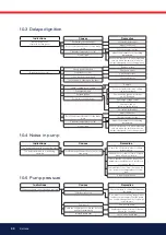
10.3 Delayed ignition

Indications

Burner pulsates at 

start with hot flue gases

Burner pulsates at start

Causes

Excessively strong draught

Excessive pressure drop across the brake 

plate

Preheater temperature too low

New oil type

Nozzle partially blocked

Oil pressure too low

Flue is blocked or damaged

The fan wheel is slipping on the shaft

Pump coupling loose or worn

Preheater blocked

Delayed ignition

Excessively strong draught

Excessive pressure drop across the brake 

plate

Preheater temperature too low

New oil type

Remedies

Correct boiler draught

Adjust the burner

Check preheater function

Adjust the preheater's set operating 

temperature

Ensure that the new oil's physical parame-

ters are within the limits for which the 

burner is designed. If not, change the oil.

Replace nozzle

Check and adjust

Check and correct

Check and tighten

Replace

Check the ignition electrode setting, 

(see technical data)

Check that the ignition electrodes 

are not damaged

Check high voltage cables

Check position of 

nozzle assembly setting

Correct boiler draught

Adjust the burner

Check preheater function

Adjust the preheater's set operating 

temperature

Ensure that the new oil's physical parame-

ters are within the limits for which the 

burner is designed. If not, change the oil.

Indications

The burner pump emits noise during start

The burner pump emits noise during 

operation

10.4 Noise in pump

Causes

Insufficient negative pressure on the suction 

side pump

Remedies

Check the oil system in order to reduce 

pressure drop

Rebuild the oil system to form a solution 

with a transport oil pump

Check that the oil used has the physical 

parameters that the burner is rated for. If 

not, change the oil.

Temperature of the oil from the tank is too 

low, increase the temperature of oil from 

tank

Clean the pump filter

10.5 Pump pressure

Indications

The burner pump can not build up pressure

Causes

No oil

Oil viscosity too low

Pump worn

Pump run using impure oil that has worn the 

pump out prematurely

Blocked pump filter

Remedies

Check that there is oil and that it reaches 

the pump

Check that the oil reaching the pump has 

the physical parameters that the pump 

can handle. Change the oil or the pump's 

oil parameters

Replace the pump

Replace pump and install self-cleaning 

filter in the oil system

Check, clean pump filter

Summary of Contents for B 55-2

Page 1: ...Providing sustainable energy solutions worldwide 178 072 66 1 2019 09 26 Installation and maintenance instruction B 55 B65 Original translation of Installation and maintenance instruction...

Page 2: ...le Beispiel exempel Manuels dans d autres langues www bentone com download ou scannez le code QR Saisir le num ro d article du br leur sur votre plaque signal tique consultez l illustration et s lecti...

Page 3: ...21 5 8 Hydraulic air adjustment __________________________ 22 5 9 Air setting_______________________________________ 22 6 Maintenance________________________________________ 23 6 1 Servicing the burne...

Page 4: ...elative humidity no condensation Temperature 20 to 60 C Check that the burner is compatible with the boiler s output range The label information on the rating plate refers to the burner s minimum and...

Page 5: ...tch this must be equipped with a hatch opening switch connected to the burner s safety system When in operation the burner s noise level can exceed 85 dBA Use hearing protection The burner must not be...

Page 6: ...h Change cleaning Brake plate 1 Year Change cleaning 3000h Change cleaning Motor 1 year 3000 hrs Cuppling chaft 1 year control change 3000h control change Fan wheel 1 Year Change when dirty unbalance...

Page 7: ...blend as defined in DIN V51603 6 and is used for Water heating generators Hot air generators these require LMO 24 255 C2E 2 1 Dimensions B 55 B65 H I A D E F G B C Type Motor supply Main supply Sound...

Page 8: ...ing field B 55 2 13 0 67 5 kg h 155 800 kW 2 3 Working field B 55 3R 13 0 64 0 kg h 155 760 kW 2 4 Working field B 65 2 22 0 99 5 kg h 260 1180 kW 2 5 Working field B 65 3R 24 0 99 0 kg h 285 1170 kW...

Page 9: ...bar 8 25 bar depending on pump model Because of the various boiler types with varying furnace geometries and furnace loads it is impossible to commit to a certain scattering angle or a specific distri...

Page 10: ...6 195 5 00 18 62 220 190 19 52 231 199 20 39 242 208 21 22 252 216 5 50 20 48 243 209 21 47 255 219 22 43 266 229 23 34 277 238 6 00 22 34 265 228 23 42 278 239 24 47 290 250 24 46 302 260 6 50 24 20...

Page 11: ...84 259 223 5 00 22 03 261 225 22 79 270 232 23 55 279 240 24 27 288 247 5 50 24 23 287 247 25 07 297 256 25 91 307 264 26 70 317 272 6 00 26 43 313 270 27 49 326 280 28 27 335 288 29 13 345 297 6 50...

Page 12: ...10 Fuse 11 Indicating lamp Stage 3 12 Switch ll llll 13 Indicating lamp Stage 2 14 Switch l ll 15 Indicating lamp Stage 1 16 Switch 0 l 17 Motor 18 Adjustment device air damper 19 Scale air regulatio...

Page 13: ...former 35 Photocell 36 Ignition wires 37 Air damper 38 Air intake 39 Solenoid valve bloc Stage 2 40 Connecting pipe 41 Solenoid valve 42 Adjustment device Nozzle assembly 43 Nozzle assembly adjustment...

Page 14: ...ntenance 3 1 1 Installation and maintenance instructions The maintenance instructions supplied with the burner must be kept at an easily accessible location in the boiler room 3 1 2 Instructions The u...

Page 15: ...15 Bentone 4 Installation 4 1 Handling and lifting instruktion figure 1 Option The lifting aid we used here are available as spare parts Figure 1...

Page 16: ...aning filters are recommended for oils of a higher viscosity or oils that contain significant impurities Oil affected parts shall be selected in materials that are capable of withstanding the medium s...

Page 17: ...boiler door to reduce radiated heat 9 Install the burner body on the flange 10 Lock the burner body using with the nut nuts 11 Connect the oil pipes to the pump refer to the chapter servicing of burn...

Page 18: ...ge 2 15 Damper motor Closed 0 Blue cam Stage 1 25 Orange cam MV 2 40 Black cam Stage 2 50 Red cam The black cam for Stage 2 MV 2 must be placed between the cams for Stage 1 and Stage 2 The positions o...

Page 19: ...a matter of a basic setting that should be adjusted retrospectively once the burner has started A flue gas analysis and soot quantity measurement must be carried out when fine tuning the burner Recome...

Page 20: ...y B55 Insert scale 5 3 Set values for nozzle assembly B65 5 4 Set values for air damper B55 5 5 Set values for air damper B65 Insert scale Air 0 15 30 45 60 75 90 100 200 300 400 500 600 700 800 Air 0...

Page 21: ...Stage 1 and Stage 2 by means of a hydraulic piston Three nozzles Nozzle assembly regulation adjusts the position of the brake plate between Stage 2 and Stage 3 by means of a hydraulic piston Low load...

Page 22: ...duce or out to increase The position of the dam per can be read from the damper scale G Carry out flue gas analysis to check the air settings 5 9 Air setting When the burner s power stage has been sel...

Page 23: ...together and secure with the nuts H 10 Open the boiler spectacle flange to access the burner pipe 11 Remove and clean the burner pipe 12 Install the burner pipe make sure you install the drainage hol...

Page 24: ...intake Lubricate the damper shaft if applicable 6 Re engage the damper motor 7 Fit the intake grille over the air intake 8 Slide the burner together and secure it with the nuts E 9 Connect the Eurost...

Page 25: ...t is important that the screw is at right angles to the plane of the shaft 10 Release the damper motor and lock it at 30 11 Fit the mounting plate by guiding the link arm into the attachment point on...

Page 26: ...K 5 Transfer the pump coupling to the new pump and adjust to give the same spacing between the pump and pump coupling as before K 6 Fit the oil pump on the burner and tighten the screws J It is import...

Page 27: ...the combustion Use caution when operating the burner surfaces may be hot 6 6 Check oil line seals Once the burner has been installed and commissioned the seals of the various coupling elements should...

Page 28: ...ibration level are 5 0 mm s Check all bolts and nuts for correct torque Check fan wheel for damage and contamination Change when dirty unbalanced Check motor bearings If worn change motor bearings Use...

Page 29: ...t the operating switch to Stage 2 II Reduce the air volume Turn orange cam towards 0 Increase the air volume Turn orange cam towards 90 Adjust the operating switch back to low capacity and check Stage...

Page 30: ...check Stage 2 Adjust the operating switch to Stage 1 I Reduce the air volume Turn orange cam towards 0 Increase the air volume Turn orange cam towards 90 If the orange cam is moved change the black ca...

Page 31: ...capacity 225 l h 294 l h Max pressure on the suction and return side 4 bar 7 3 Mounting dismounting by pass plug In a 2 pipe system excess oil is led back direct to the oil tank In a 1 pipe system the...

Page 32: ...and produces a drop in the oil pressure The spring in the regulating valve presses the regulating piston forward until it seals in port P This cuts off the oil flow to the nozzle and ensures that the...

Page 33: ...l quality according to current standards On commissioning with an empty tube system the oil pump should not be run without oil for more than 5 min a condition is that the pump is being lubricated duri...

Page 34: ...same wiring as the existing component or the specified alternative arrangement 5 Turn on the mains power 6 Check the function of the new component 7 Start the burner Check combustion Note When servici...

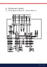
Page 35: ...35 Bentone 165 205 41 9 Oil burner control 9 1 Wiring diagram LMO24 255 B55 2H B65 2H...

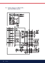
Page 36: ...36 Bentone 9 2 Wiring diagram LMO24 255 B55 2H R B65 2H R...

Page 37: ...at A spark is formed The air damper motor opens the damper to low load position The burner motor starts the prepurge goes on till the prepurge period expires and the solenoid valve 1 opens 2 2 Solenoi...

Page 38: ...by pressing and holding the reset button for 3 seconds The number of flashes below is repeated with a pause in between 2 flashes No flame signal when safety time expires 4 flashes False light during s...

Page 39: ...ent light Check high voltage wiring and ignition electrodes Check preheater function Symptom Burner does not start Burner pre ventilates Burner stops Causes Fuse blown Boiler thermostat has not reset...

Page 40: ...ht Adjust the burner Check preheater function Adjust the preheater s set operating temperature Ensure that the new oil s physical parame ters are within the limits for which the burner is designed If...

Page 41: ...Address Test performed by Postal address Company name Tel no Boiler Type Make Power kW Bentone Burner Type Model Serial no Fuel Step 1 Step 2 Step 3 Draught in fireplace Fan Press mbar Filter smoke nu...

Page 42: ...perature If the burner will not start Press the reset button on the relay Check that the thermostats are correctly adjusted Don t forget the room thermostat check that any fusesare intact and main swi...

Page 43: ...171 905 28...

Page 44: ...Enertech AB P O Box 309 SE 341 26 Ljungby www bentone se www bentone com...

Reviews: