18
Bentone
165 205 35
Choice of nozzle B65-2H/B65-2/
B65-2R
Burner output
770 kW
Nozzle Stage 1
770 x 0,6 = 460 kW
460 / 11,86 = 38,8 kg/h
Nozzle Stage 2
770 x 0,4 = 310 kW
310 / 11,86 = 26,1 kg/h
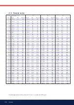
According to the table of nozzles this gives the
following nozzles.
Stage 1
8,50 Gph
Stage 2
6,00 Gph
Pump pressure : 14 bar
Basic settings B65-2H
Nozzle assembly
Stage 2 = 15
Air adjustment
Stage 1 = 25°
Stage 2 = 65°
Each graduation on the scale corresponds to 10°
Basic settings B65-2
Power outputs and nozzle choice from example.
Nozzle assembly
Steg 2 = 15
Damper motor
Closed = 0° Blue cam
Stage 1 = 25° Orange cam
MV 2 = 50° Black cam
Stage 2 = 65° Red cam
The black cam for Stage 2 (MV 2) must be placed
between the cams for Stage 1 and Stage 2. The
positions of MV 2 are determined by the boiler
characteristics when switching between stages, but
for a basic setting the black cam should be placed in
the middle.
Basic settings B65-2R
Power outputs and nozzle choice from example
Nozzle assembly
Stage 1 = 0
Stage 2 = 15
Damper motor
Closed = 0° Blue cam
Stage 1 = 25° Orange cam
MV 2 = 40° Black cam
Stage 2 = 50° Red cam
The black cam for Stage 2 (MV 2) must be placed
between the cams for Stage 1 and Stage 2. The
positions of MV 2 are determined by the boiler
characteristics when switching between stages, but
for a basic setting the black cam should be placed in
the middle.
Choice of nozzle B65-3R
Burner output
880 kW
Nozzle
880 / 3 = 293 kW
293 / 11,86 = 24,7 kg/h
According to the table of nozzles this gives the
following nozzles:
Stage 1
5,50 Gph
Stage 2
5,50 Gph
Stage 3
5,50 Gph
Basic settings B65-3R
Power outputs and nozzle choice from example
Nozzle assembly
Stage 1/2 = 5
Stage 3 = 20
Damper motor
Stage 1 = 10° Blue cam
MV 2 = 30° Black cam
Stage 2 = 44° Orange cam
MV 3 = 60° Green cam
Stage 3 = 80° Red cam
The cams for Stage 2 (MV 2) and Stage 3 (MV 3) must
be placed between the cams for Stage 1 and Stage 2,
and between Stage 2 and Stage 3, respectively. The
positions of MV 2 and MV 3 are determined by the
boiler characteristics when switching between stages,
but for a basic setting the cams (MV2 and MV3)
should be placed in the middle.
5. Basic settings
5.1 Typical basic settings for B65-2H/B65-2
B65-2R/B65-3R


