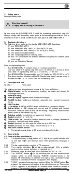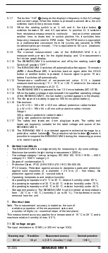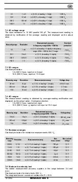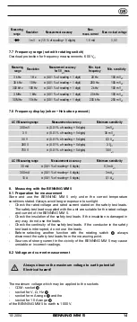
10/ 2004
BENNING MM 5
16
- Connect the red safety test lead to the socket
for V, Ω, Hz on the
BENNING MM 5.
- Contact the measuring points with the safety test leads. If the test lead
resistance between the COM socket
and the socket
for V, Ω, Hz on
the BENNING MM 5 is lower than 30 Ω the built-in buzzer is activated.
See fig. 8:
Continuity testing with buzzer
8.6 Frequency testing
- With the rotating switch
, select the desired function (Hz) on the
BENNING MM 5.
- Connect the black safety test lead to the COM socket
on the
BENNING MM 5.
- Connect the red safety test lead to the socket
for V, Ω, Hz on the
BENNING MM 5. Remember the minimum sensitivity for frequency
measurements using the BENNING MM 5.
- Contact the measuring points with the safety test leads and read the
measurement result on the digital display
on the BENNING MM 5.
See fig. 9:
Frequency measurement
9. Maintenance
Before opening the BENNING MM 5, ensure that it is not
connected to a source of voltage! Electrical hazard!
Any work required on the BENNING MM 5 when it is under voltage must be
done only by a qualified electrician. Special steps must be taken to prevent
accidents.
Before opening the BENNING MM 5, remove it from all sources of voltage as
follows:
- First remove both safety test leads from the measurement points.
- Remove both safety test leads from the BENNING MM 5
- Turn the rotating switch
to “OFF”.
9.1 Securing the unit
Under certain circumstances, the safety of the BENNING MM 5 can no longer
be guaranteed. This may be the case if:
- there are visible signs of damage on the unit,
- errors occur in measurements,
- the unit has been stored for a long period of time under the wrong
conditions, and
- if the unit has been subjected to rough handling during transport.
In these cases, the BENNING MM 5 must be switched off immediately, removed
from the measuring points and secured to prevent it from being used again.
9.2 Cleaning
Clean the outside of the unit with a clean dry cloth. (Exception: any type of
special cleaning cloth). Never use solvents or abrasives to clean the testing unit.
Ensure that the battery compartment and the battery contacts have not been
contaminated by electrolyte leakage.
If any electrolyte or white deposits are seen near to the battery or in the battery
compartment, remove them with a dry cloth, too.
9.3 Battery replacement
Before opening the BENNING MM 5, ensure that it is not
connected to a source of voltage! Electrical hazard!
The BENNING MM 5 is powered by two 1.5 V micro batteries. The batteries must
be replaced (see fig. 10) when the battery symbol appears in the display
.
To replace the batteries, proceed as follows:
- First remove the safety test leads from the measurement circuit.
- Remove the safety test leads from the BENNING MM 5.
- Turn the rotating switch
to “OFF”.
- Remove the protective rubber holster
from the BENNING MM 5.
- Lay the BENNING MM 5 on its front and loosen the screw from the cover of
the battery compartment.
- Lift the battery-compartment cover (at recesses in housing) off the bottom
part.

