


89000109-002
xVue Touch Installation Manual
Rev 2
Page 6-18
© Honeywell International Inc. Do not copy without express permission of Honeywell.
For Use in Non-Certified Aircraft
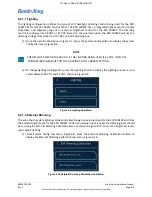
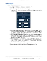
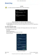
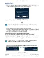
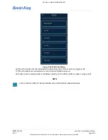
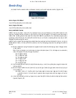
(1) From the PFD sub-menu, Figure 6-23, press the VSI button to display the VSI Selection menu,
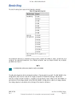
Figure 6-25 VSI Selection Menu
(2) Select desired VSI Range
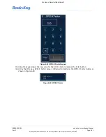
(3) Press the Back-Arrow button to return to the PFD sub-menu.
(4) Verify that the desired VSI Range is reflected correctly on the VSI button, shown in Figure 6-23.
6.2.2.2 Airspeed
The KSD renders the color bands and lines on the PFD Airspeed Tape that are defined through the
following rules:
(1) V
NE
: Never Exceed speed. If V
NE
is defined the airspeed tape displays a red and white barber pole
band from V
NE
to the max tape value. A Radial Red Line is displayed on the airspeed tape at V
NE
.
(2) V
NO
: Normal Operations Maximum Structural Cruise speed. For airplane with no published V
NO
,
set V
NO
= V
NE
. A yellow band is displayed on the airspeed tape between V
NO
and V
NE
. V
NO
must
be less than or equal to V
NE
.
(3) V
FE
: Maximum Flaps Extended speed (top of white band).
(4) V
S1
: No Flaps Stall speed. A green band is displayed on the airspeed tape between V
S1
and V
NO
.
V
S1
must be less than V
NO
.
(5) V
SO
: Full Flaps Stall speed (bottom of white band). A white band is displayed on the airspeed tape
between V
SO
and V
FE
. V
SO
must be less than V
FE
.
(6) V
YSE
: Single engine best rate of climb speed for a multi-engine airplane. A blue horizontal line is
displayed at the V
YSE
airspeed. The V
YSE
V-Speed is only made available for setting when the
Single/Multi Engine parameter is set to Multi.
(7) V
MC
: Minimum Control Airspeed with Critical Engine Inoperative. A red horizontal line is displayed
at the V
MC
airspeed. The V
MC
V-Speed is only made available for setting when the Single/Multi
Engine parameter is set to Multi.
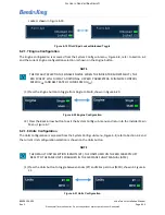
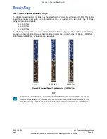
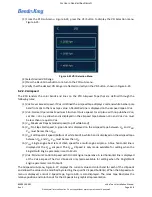
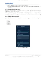
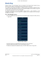
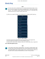
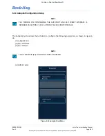
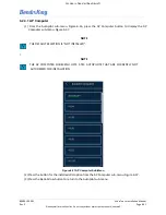
The Airspeed sub-menu, Figure 6-27, displays the current value and color band for each of the V-Speeds
and allows the values to be modified by selecting the specific V-Speed button(s). When the Airspeed sub-
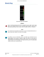
menu is displayed, a mock V-Speed tape, Figure 6-26, is also displayed. The mock tape illustrates the
relative position and color bands for the V-Speeds in a graphical representation.


