


System description
17
EDS309x_D00012_03_M_XXEN/11.2014
3.3.3
Definitions
I
L
= Locating current that flows through the locating current injector while the fault location
is running (EDS mode).
I
Δ
L
= Locating current measured by the insulation fault locator (EDS mode).
I
Δ
n
= Residual current produced by an insulation fault (RCM mode).
3.3.4
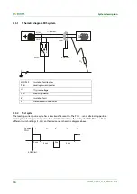
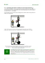
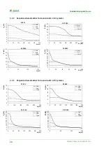
Currents in the EDS system
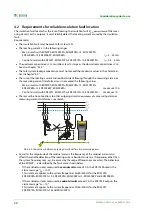
As an addition to the schematic diagram on page 16, here the path of the residual currents and the
locating current is shown:
The following residual currents flow through the measuring current transformer of the EDS195P:
The locating current caused by the insulation fault
R
F-N
The residual currents
I
Δ
n
that flow through the system leakage capacitances
C
E-V
and
C
E-N
, or that are caused by
R
F-V
and
R
F-N
Transient leakage currents that are caused by switching and control activities in the system
Low-frequency leakage currents generated by the use of converters
.............
Locating current circuit due to the insulation fault
R
F-N
. .. .. ..
Residual currents
I
Δ
n
(example)
I
Δ
L
Locating current measured by the EDS195P
C
E-V
Upstream capacitances, system leakage capacitances upstream of the
measuring current transformer
C
E-N
Downstream capacitances, system leakage capacitance downstream of
the measuring current transformer
R
F-V
Insulation fault upstream of measuring current transformer
R
F-N
Insulation fault downstream of the measuring current transformer
U
n
IT-System
PSA...
EDS195P
PE
R
F-N
R
F-V
C
E-N
C
E-V
PGH...
1
2
3
I
Δ
n
I
Δ
L
I
L
Summary of Contents for EDS3090
Page 6: ...Table of Contents 6 EDS309x_D00012_03_M_XXEN 11 2014...
Page 26: ...Considerations prior to use 26 EDS309x_D00012_03_M_XXEN 11 2014...
Page 62: ...Frequently Asked Questions 62 EDS309x_D00012_03_M_XXEN 11 2014...
Page 65: ......
Page 66: ......
Page 67: ......


