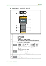


Operation
47
EDS309x_D00012_03_M_XXEN/11.2014
6.12.3 Insulation fault location in diode-decoupled DC systems
In diode-decoupled DC systems equalising currents occur in and between the decoupled circuits.
The direction and magnitude of these equalising currents is dependent on voltages in the system,
the characteristics of the decoupling diodes and the characteristics of the loads.
On the usage of the insulation fault location system EDS309… in such systems these equalising cur-
rents make themselves apparent and can degrade the accuracy of the measurement. For this reason
we recommend the usage of the EDS309… in diode-decoupled systems as shown in the sketch on
the next page.
During this process please note:
Always use two measuring clamps of the same type.
Attention: this clamp type must also be set on the EDS195P.
For this purpose use the EDS195P set (see ordering data, page 59).
Take into account the maximum length of the coax cable of 10 m per measuring clamp.
The usage of two measuring clamps results in a sensitivity loss of around 10 %.
It is imperative both measuring clamps are used such that the direction of the flow of energy
corresponds to the arrow printed on the clamp.
Example: The central insulation monitoring device in a DC system without permanently installed in-
sulation fault location system (EDS) has signalled an insulation fault that is below the insulation value
that can be located using the EDS system. Once all the instructions from chapter "4. Considerations
prior to use" have been followed, fault location in a modified form can be started. Proceed as follows
during this process:
1. Read the actual insulation resistance on the insulation monitoring device. If the value read for
the insulation resistance is lower than the maximum insulation fault that can be located by the
EDS system, two appropriate identical measuring clamps (e.g. 2 x PSA3020 or
2 x PSA3052) are required for the insulation fault location.
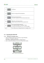
2. Switch on the EDS195P without a current transformer by pressing the
button. The device
undertakes a self-test and outputs the error message "No CT connected".
3. Now select the type of measuring clamp(s) to be connected using the
button. The device
undertakes a further self-test and outputs the error message "No CT connected" because a cur-
rent transformer is not connected
4. Then connect the pre-selected measuring clamp(s) to the EDS195P. The device undertakes a
further self-test and is then in the EDS mode. "I
Δ
L
" appears in the first line of the display
5. Connect the PGH18… to the locating current injection points are shown on page 48.
6. Start the EDS system:
Switch on the PGH18…. The "ON" LED illuminates and the two and LEDs flash in synchronism
with the test cycle. If there is no activity indicated on the LEDs, check the supply voltage and
the fine-wire fuse fitted in the PGH18….
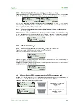
7. Insulation fault location in the system:
– Place a measuring clamp around each of the supply cables to the redundantly supplied
loads. During this process ensure that the clamp is placed around all related load supply
cables for a diode-decoupled load.
Risk of electric shock!
On touching live uninsulated conductors, death or serious injury may be caused.
For this reason avoid any contact whatsoever with active conductors on con-
necting the PGH and positioning the measuring clamp.
DANGER
Summary of Contents for EDS3090
Page 6: ...Table of Contents 6 EDS309x_D00012_03_M_XXEN 11 2014...
Page 26: ...Considerations prior to use 26 EDS309x_D00012_03_M_XXEN 11 2014...
Page 62: ...Frequently Asked Questions 62 EDS309x_D00012_03_M_XXEN 11 2014...
Page 65: ......
Page 66: ......
Page 67: ......


