6 720 611 443 GB (05.04)
Maintenance
37
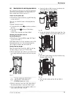
Diaphragm in mixer unit
B
Open mixer unit (29).
B
Carefully withdraw diaphragm (443) from fan intake
tube and check for soiling and splits.
Fig. 58
B
Carefully refit diaphragm (443) the correct way round
into the fan intake tube.
B
Seal the mixer unit (29).
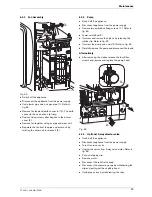
Siphon
B
Unscrew the clip and disconnect the pipe to the
siphon.
B
Remove the drain plug to drain the siphon.
B
Unscrew the securing nut from beneath the side
facia and remove the siphon. Refer to figure below.
B
Refit and prime the siphon.
Fig. 59
Expansion vessel
The expansion vessel should be checked once a year.
B
Depressurise appliance.
B
If necessary, adjust expansion vessel charge pres-
sure to static head of the heating system.
Heating system pressure
B
The pointer on the pressure gauge should be 1 bar.
B
If the pointer is below 1 bar (when the system is
cold), water should be added until the pointer is
1 bar again.
B
Max. pressure
of 2.5 bar when the heating system
water is at maximum temperature must not be
exceeded. If this pressure is exceeded then an extra
expansion vessel must be fitted in the system return
as close to the appliance as possible.
B
If the system does not retain the pressure, the expan-
sion vessel and the heating system should be
checked for leaks.
Electrical wiring
B
Check the electrical wiring for physical damage and
replace any damaged wires.
B
Take care not to damage diaphragm
(443) when removing and refitting it.
i
The flaps of the diaphragm (443) must
open upwards.
1.
2.
3.
443
29
6 720 610 790-07.2R
i
Fill the system using the WRAS approved
filling loop.
Condensate
Drain
Siphon
Drain Plug
6 720 611 441-07.1O


