


19
Vertigo XG
Installation and Quick Start Guide
Cabling the Vertigo XG Unit
Once the Vertigo XG chassis is securely mounted in an equipment rack, you can connect
the required cables to the rear connectors of the Vertigo XG unit.
To cable the Vertigo XG
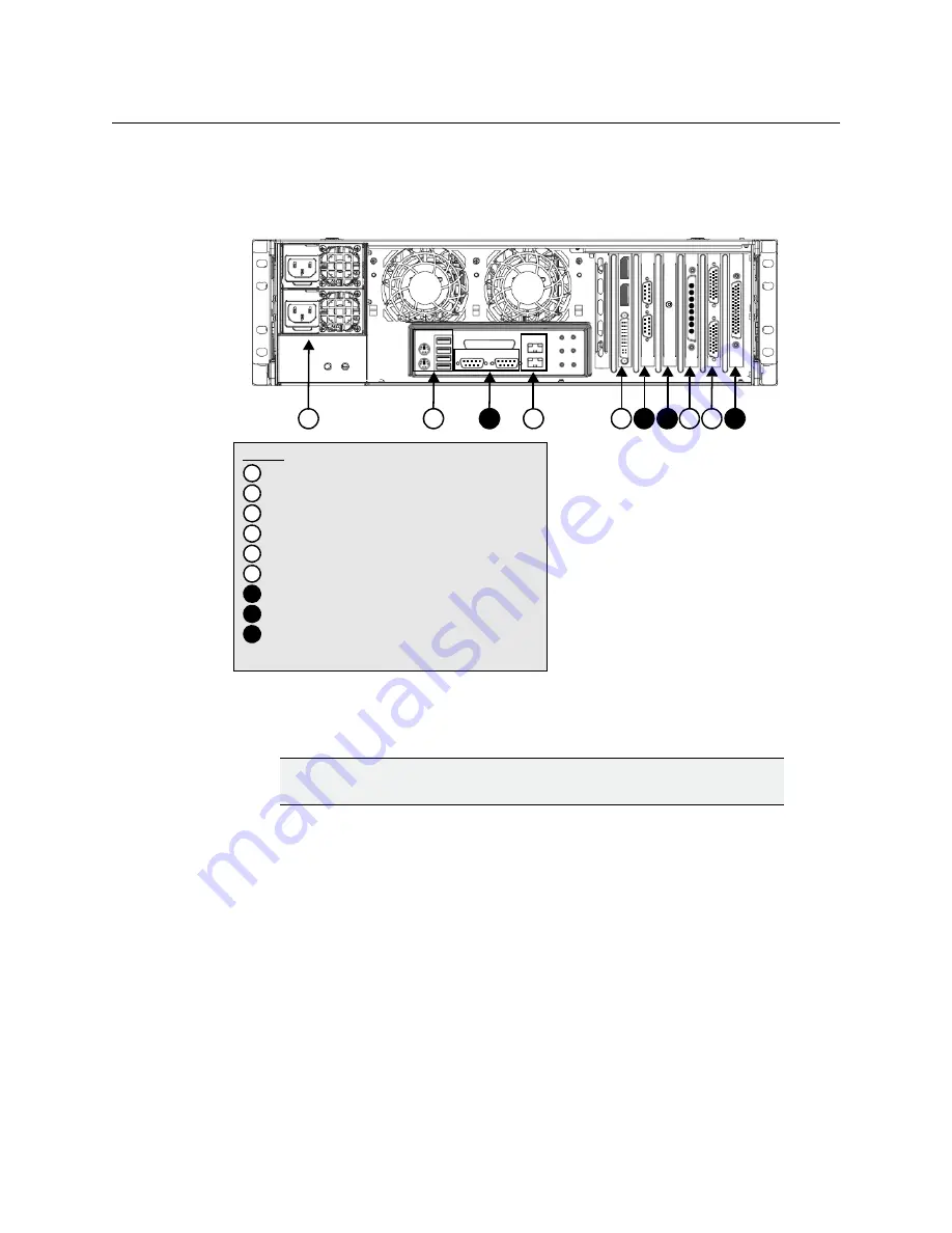
1 Connect the two (2) AC power cables to the power supply sockets on the rear panel of
the Vertigo XG chassis.
2 Connect the keyboard and mouse to the USB connectors on the rear panel of the
Vertigo XG. Two PS/2 connections are also available on the rear panel, should you
prefer to use another type of keyboard and mouse.
3 Connect to a computer monitor to the DVI or DisplayPort connector on the rear panel
of the Vertigo XG. If you prefer, you can use the VGA/DVI monitor adapter to connect
the Vertigo XG device to VGA monitor.
4 Connect the Vertigo XG device to the Local Area Network (LAN) by connecting ethernet
cables to the two (2) Network Ethernet connectors.
The Vertigo XG’s two network ethernet adapters are teamed together (connect 2 cables
to the 2 NIC cards at the same time) to form a third virtual adapter. In the event of an
adapter, cable or switch failure, the network interface fails over to the healthy adapter.
If you only have one cable connected, then the teaming is still in effect, but all traffic
will be over that one cable. If that NIC fail, you will have to manually move the cable to
the other NIC.
WARNING
DO NOT plug the power cables into AC power sockets yet.
Legend
1
2
4
3
5 6
7
7
8
9
*
The numbers correspond to the steps in the cabling procedure
1
Power supplies
2
Mouse & keyboard connectors
3
DVI Monitor connectors
4
Ethernet Network connectors
5
SDI Video I/O connector
6
Discrete (AES) Audio connector(s)
Option: Automation system connections (RS-232 or RS-422)
7
Option: Time Code Card connector
8
Option: GPI Card connector
9
LTC
IN
Summary of Contents for grass valley VERTIGO XG
Page 12: ...xii Table of Contents...
Page 14: ...2 Introduction...


