31
NV9601
User’s Guide
How to Configure MD Destinations
Follow these guidelines.
1 Click any line in the display portion of the panel graphic. (A single click is all that is
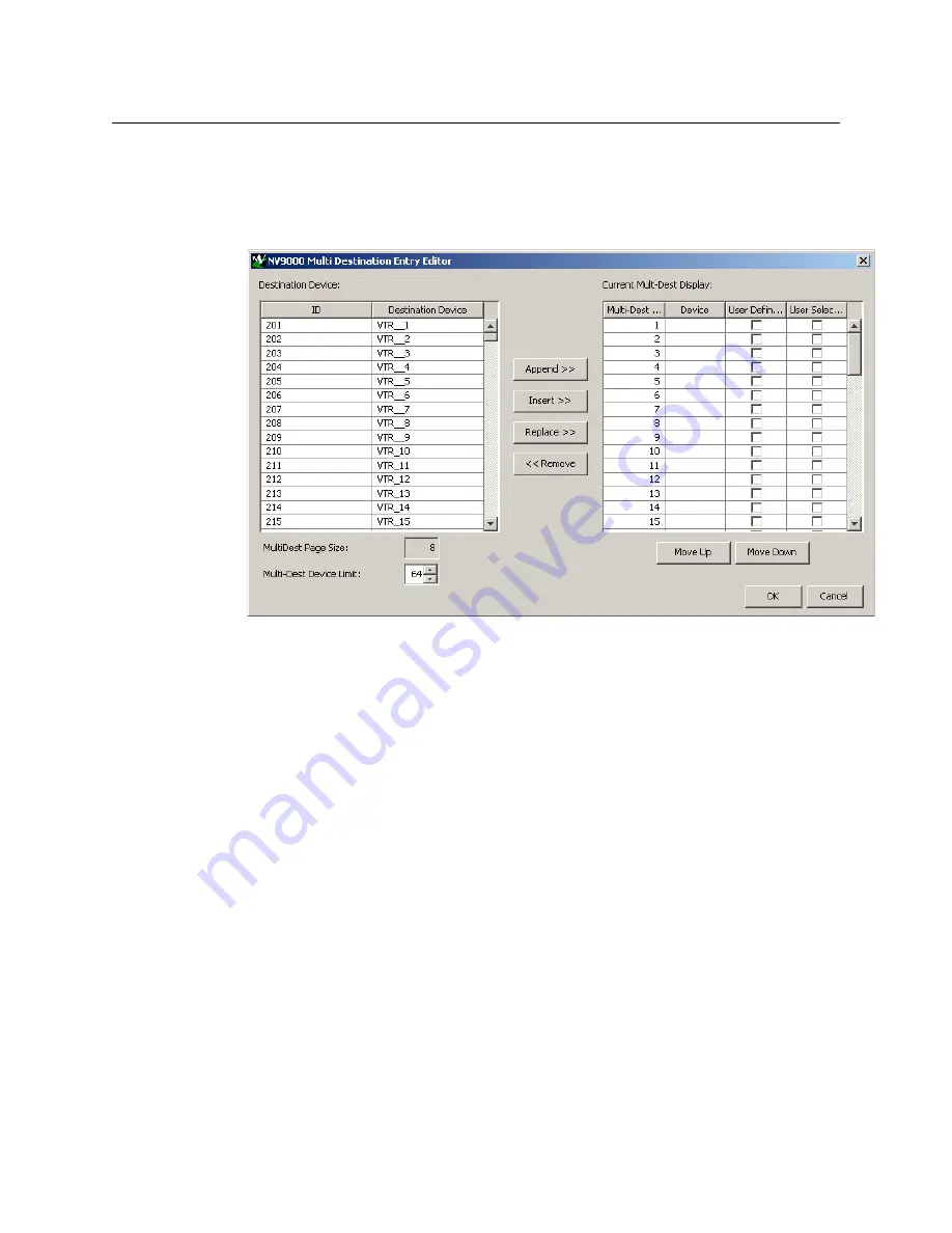
required.) A dialog appears. This is the multi-destination entry editor:
On the left is a list of
all
destinations defined in the NV9000 system. On the right is a
table of the MD destinations you are defining. The number of rows in this table is equal
to the maximum number of MD destinations your configuration allows.
To define an MD destination, select a destination on the left and copy it, using either
the ‘Append’ button, the ‘Insert’ button, or the ‘Replace’ button, to the right.
The ‘Append’ button
appends
the selected destination to the end of your set of MD
destinations.
The ‘Insert’ button places the selected destination immediately
above
whatever MD
destination you have highlighted on the right.
The ‘Replace’ button
replaces
whatever MD destination you have highlighted on the
right.with the selected destination from the left.
The ‘Remove’ button
removes
highlighted MD destinations from the right.
At the bottom left, there is a scroll box in which you can adjust the maximum number
of MD destinations. (The page size is indicated as fixed at 8 entries. You cannot change
the page size.)
At the bottom right, are ‘Move Up’ and ‘Move Down’ buttons. You can use these to
adjust the position in the list of any MD destination.
After you have finished configuring MD destinations, click OK (or cancel, if you want to
discard your entries). The MD destinations you have configured now appear in the
display section of the panel graphic. They will subsequently appear in the display of the
panel when it is operating in MD mode.
You can edit the set of MD destinations later, adding or removing entries as you wish.
Summary of Contents for Grass Valley NV9000
Page 1: ...www grassvalley com User s Guide VERSION 2 4 UG9601 04 2015 07 02 NV9601 NV9000 CONTROL PANEL...
Page 6: ...vi Notices...
Page 72: ...62 Operation Test...
Page 76: ...66 Technical Details Drawings Fig 6 1 Front View of the NV9601 3 00 76 2 3 47 88 1 19 0 482 6...
Page 78: ...68 Technical Details Drawings...


