


GUIDE TO INSTALLATION AND OPERATION
FIO-1901-R |
11
The table below lists the various status icons that can appear, and how they are to be interpreted.
•
In cases where there is more than one possible interpretation, read the error message in the iControl window to
see which applies.
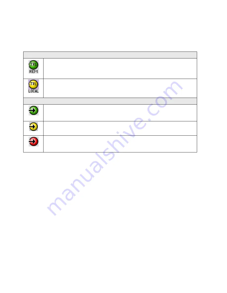
Table – iControl Status Icon interpretation
Icon #1 – Manual Card Configuration
(green)
Remote card control activated. The iControl interface can be used to operate the card
(yellow)
Local card control active, The card is being controlled using the Densité frame control
panel, as described in section 3.2. Any changes made using the iControl interface will have
no effect on the card.
Icon #2 – In A status
(green)
Signal detected and valid.
(yellow)
No lock
(red)
No signal
No rear
Section 2.
The left portion of the window contains access buttons for all the parameter groups, which become
highlighted when they are selected; the main panel (3) then displays the group’s set of parameters. Each of the
groups is described in detail below.
Section 3.
The main panel contains all the parameters specific to the group selected.
Each of the panels associated with the groups accessed from the buttons in Section 2, and shown in Section 3, is
described individually in the following sections.


