


Page
27 ©
BEKA 2017 All rights reserved!
...a product of
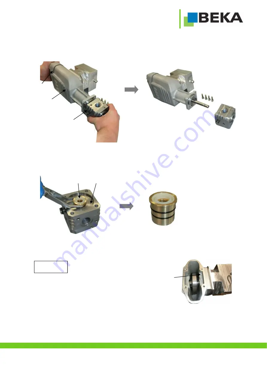
12. Step:
For a smoother demounting, the cover (N) can be fastened with the pump housing again via the 4 cylinder screws (M). Now pull off
the connection piece (Q) from the pump housing (O).
13. Step:
Pull out the sealing bush (R) with a gripper from the connection piece (Q).
Now the sealing kit can be replaced by a new one.
14. Step:
The device shall be reassembled in reverse order.
All sealings have to be installed properly and must
have no damages. Furthermore the pump housing
(O) shall be filled with oil up to the “max. level”. Also
observe the notes in step 10.
Attention!
O
N
Q
Q
R
O


