37
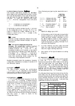
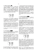
Step 7
Lower display
Using the
&
or
*
button select
di5P-2
in the configuration menu and press
(
to select if the lower display function.
The Rate Totaliser is required to display
both total flow and the rate of flow so the
lower display is required. Using the
&
or
*
button select
5td
and press
)
to
enter the selection and return to the
di5P-2
prompt in the configuration
menu.
See 6.11
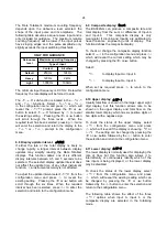
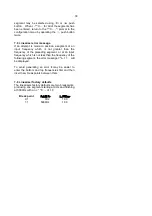
Step 8
Position rate & total decimal points
Select
dP
from the configuration menu
and press
(
. The upper display
already defined as the total display by
function
di5P-1
will be activated and
identified by the Total annunciator. Using
the
&
or
*
push button position the
decimal point in front of the second least
significant digit to give a total display
resolution of 0.00.
Pressing the
(
button will show the rate
display, but in the upper display position
with the Rate annunciator activated.
Using the
&
or
*
push button position
the decimal point to the right of the least
significant digit so that it is not visible to
give a total display resolution of 1.
Finally press the
)
button to enter the
selections and return to the
dP
prompt in
the configuration menu.
See 6.12
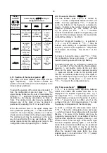
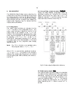
Step 9
Enter the flowmeter K-factor
K-factor is the number of pulses that a
flowmeter produces per unit volume of
flow. The Rate Totaliser pulse input A is
divided by
FACtor-A
, which is adjustable
between 0.0001 and 99999; when set to
the K-factor of the flowmeter it converts
the flowmeter output into engineering
units ready for further scaling to produce
the required rate and total flow displays
Using the
&
or
*
push button select
FACtor-A
from the configuration menu
and press
(
to show the existing value
with one digit flashing. This should be
changed to
105
using the
&
and
*
push buttons to adjust the flashing digit
and the
(
button to transfer control to
the next digit and to position the decimal
point.
Finally, enter the new figure and return to
the
FACtor-A
prompt in the configuration
menu by pressing
)
. The output from
FACtor-A will now be in litres which may
be scaled to produce required rate and
total displays.
Repeat for input b using the
FACtor-b
function.
See 6.13
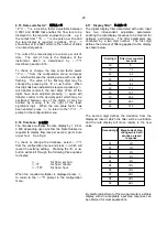
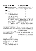
Step 10 Enter the total scale factor
The Total Scale Factor
5CALE
.
t-A
is a
dividing factor adjustable between
0.0001 and 99999 that enables total flow
to be displayed in the required
engineering units. In this example the
total flow display is required in cubic
metres. There are 1,000 litres in a cubic
metre so
5CALE
.
t-A
should be set to
1000
.
Using the
&
or
*
push button select
5CALE
.
t-A
from the configuration menu
and press
(
to reveal the existing value
with one digit flashing. This should be
changed to
1000
using the
&
or
*
push button to adjust the flashing digit
and the
(
button to transfer control to
the next digit and to position the decimal
point. Finally, enter the new value and
return to the
5CALE
.
T-A
prompt in the
configuration menu by pressing
)
.
The total flow display is independent of
the rate display.
Repeat for input b using the
5CALE
.
t-b
function.
See 6.14
Step 11 Enter the rate scale factor
5CALE
.
r-A
is a dividing factor adjustable
between 0.0001 and 99999 that enables
the input A flow rate to be displayed in
the required engineering units. The rate
display timebase is determined by
‘
t-bA5E
that is adjusted in Step 12.
In this example the rate of flow display is
required in imperial gallons.
FACtor-A
,
which was adjusted in Step 8, has an
output in Litres that must be converted to
imperial gallons. There are 4.5461
Litres in an imperial gallon therefore
5CALE
.
r-A
should be adjusted to 4.5461
Using the
&
or
*
push button select
5CALE
.
r-A
from the configuration menu
and press
(
to reveal the existing value
with one digit flashing.

