20
6.2 Accessing configuration functions
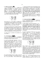
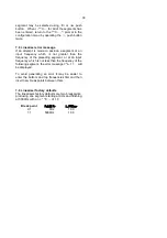
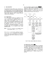
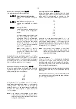
Throughout this manual push buttons are shown as
&, *, (
and
)
and legends displayed by the
instrument are shown in a seven segment font
exactly as they appear on the instrument display e.g.
inPut-A
and
FiLtEr-A
.
Access to the configuration menu is obtained by
operating the
(
and
)
push buttons
simultaneously. If the instrument is not protected by
an access security code the first parameter
FunCtion
will be displayed. If a security code other
than the default code
0000
has already been
entered, the instrument will display
CodE
. Press
(
to clear this prompt and enter the security code
for the instrument using the
&
or
*
push button to
adjust the flashing digit, and the
(
push button to
transfer control to the next digit. If the correct code
has been entered pressing
)
will cause the first
parameter
FunCtion
to be displayed. If an incorrect
code is entered, or a push button is not operated
within ten seconds, the instrument will automatically
return to the totalising mode.
All configuration functions and prompts are shown
on the upper eight digit display except the filter
which uses both the upper and lower displays.
Once within the main configuration menu the
required parameter can be selected by scrolling
through the menu using the
&
or
*
push buttons.
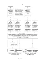
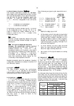
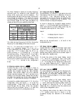
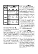
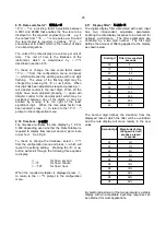
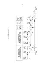
The configuration menu is shown diagrammatically
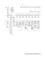
in Fig 10.
When returning to the totalising mode following
reconfiguration, the Rate Totaliser will display
dAtA
followed by
5AVE
while the new information is stored
in permanent memory.
If during configuration a button is not operated within
60 seconds, the instrument will automatically return
to the totalising mode and any configuration
changes will not be stored. When configuring a
BA384NG Rate Totaliser it is therefore advisable to
occasionally return to the totalising mode to ensure
that recent configuration changes are stored in
permanent memory.
6.3 Summary of configuration functions
This section summarises all the configuration
functions. When read in conjunction with Fig 10 it
provides a quick aid for configuring the Rate
Totaliser. If more detail is required, each section of
this summary contains a reference to a full
description of the function.
For simplicity this summary and Fig 10 only show
functions that configure both inputs and those which
configure input A. Immediately following each
function with an
A
suffix in the configuration menu is
an identical function with a
b
suffix that configures
the ‘b’ input. In this instruction manual descriptions
of ‘A’ input functions which are followed by an
identical function for the ‘b’ input are identified with
an *.
Display
Summary of function
FunCtion
Rate totaliser function
Defines the relationship of both pulse
input channels and the Rate Totaliser
display.
May be set to:
5td
Standard linear relationship
Lin
Separate 16 segment fully
adjustable lineariser in each
input channel which are
described in section 7.
See section 6.4
input-A
Input*
Contains two sub-functions:
See section 6.5
inP
.
tYPE
Configures the Rate Totaliser input to
accept one of six types of input:
oP.CoL
Open collector
●
VoLt5 L
Voltage pulse <1 >3V
VoLt5 H
Voltage pulse <3 >10V
CoiL
Magnetic pick-off
Pr.dEt
Proximity detector
●
ContACt
Switch contact
●
●
Requires input to be energised by
linking terminals 3 & 4 for input A, and
terminals 7 & 8 for input b.
See section 6.6

