12
4.2.2
Open collector input
Most Zone 2 certified flowmeters, except intrinsically
safe instruments, with an open collector output may
be directly connected to input terminals 5 & 6 or 9
&10. The flowmeter should be located in the same
Zone 2 hazardous area as the BA384NG, and the
flowmeter and associated wiring should be able to
withstand a 500V rms insulation test to earth.
The BA384NG contains a configurable debounce
circuit to prevent false triggering. Three levels of de-
bounce protection are independently available for
each input. See section 6.7.
4.2.3
2-wire proximity detector input
Most Zone 2 certified flowmeters, except intrinsically
safe instruments, incorporating a NAMUR 2-wire
proximity detector may be directly connected to a
BA384NG input, providing the operating voltage of
the flowmeter (proximity detector) is less than 7.5V.
The flowmeter should be located in the same
hazardous area as the BA384NG and with the
associated wiring be able to withstand a 500V rms
insulation test to earth.
The BA384NG contains a configurable de-bounce
circuit to prevent false triggering. Three levels of
debounce protection are independently available for
each input. See section 6.7.
4.2.4
Magnetic pick-off input
Flowmeters incorporating a magnetic pick-off to
sense flow will have a low level voltage output
unless the flowmeter incorporates an amplifier.
CoiL
in the BA384NG input configuration menu is a low
level voltage pulse input which will sense this output.
Most Zone 2 certified flowmeters, except intrinsically
safe instruments, with a low level magnetic pick-off
output may be directly connected to input terminals
5 & 6 or 9 &10.
The flowmeter should be located in the same
hazardous area as the BA384NG and with the
associated wiring be able to withstand a 500V rms
insulation test to earth. The BA384NG contains a
configurable de-bounce circuit to prevent false
triggering. Three levels of debounce protection are
independently available for each input. See
section 6.7.
4.2.5
Voltage pulse input
Two voltage pulse input ranges are independently
selectable in the BA384NG Rate Totaliser
configuration menu,
VoLt5 L
and
VoLt5 H
. When
configured for either of the voltage pulse ranges, the
Rate Totaliser’s input terminals 5 & 6 and 9 & 10
may be directly connected to most certified Zone 2
certified flowmeters, except intrinsically safe
instruments, with a high level voltage pulse output.
The BA384NG contains a configurable debounce
circuit to prevent false triggering of the instrument.
Three levels of de-bounce protection are
independently available for each input,
See section 6.7.
4.3
Remote reset
The BA384NG Rate Totaliser's total display may be
remotely reset to zero by connecting terminals RS1
and RS2 together. Permanent interconnection
inhibits totalisation. Remote resetting may be
accomplished by any mechanically operated switch
located in Zone 2 as the Rate Totaliser's reset circuit
is non incendive. The reset switch and the
associated wiring should be able to withstand a
500V rms insulation test to earth.
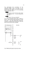
A BA384NG may also be remotely reset from the
safe area. Any switch may be used. Fig 3 illustrates
how a BA384NG may be reset from both the safe
and the hazardous area.
The BA384NG total display may also be reset when
the
&
and
*
push buttons are operated
simultaneously in the totalising mode i.e. when the
instrument is displaying flow. See 6.19
4.4 Pulse output
The BA384NG Rate Totaliser has an opto-isolated
Ex nA certified open collector pulse output which can
be configured to synchronously retransmit either of
the two pulse inputs, or a scaleable pulse when the
least significant digit of total display is incremented.
The output has the following electrical parameters:
V max
=
30V dc
Imax
=
10mA
Ron
=
60
Ω
+ 3V
Roff
=
1M
Ω
Providing the BA384NG Rate Totaliser is correctly
installed in Zone 2, the pulse output may be
connected to any dc circuit in Zone 2 or in the safe
area. In normal operation the maximum supply
voltage should not be greater than 30V dc and the
maximum current should not be greater than 10mA.

