11
4.2
Pulse inputs
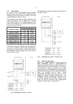
As shown in Fig 3 both BA384NG Rate Totaliser
inputs may be connected to Zone 2 hazardous area
flowmeters with a wide variety of outputs, or to safe
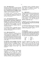
area flowmeters as shown in Fig 4.
The following table shows the Rate Totaliser's input
switching thresholds when configured to operate
with various sensors. For reliable operation input
pulses must fall below the lower threshold and rise
above the upper threshold.
Flowmeter output
Switching thresholds
Lower
Upper
Switch contacts
100
Ω
1000
Ω
Proximity detector
1.2mA
2.1mA
Open collector
2k
Ω
10k
Ω
Magnetic pick-off
0mV
40mV peak
Voltage pulse low
1.0V
3.0V
Voltage pulse high
3.0V
10.0V
Flowmeters with a switch contact, proximity detector
or an open collector output require energising to
determine their state which is achieved by linking
two BA384NG terminals together for each input as
shown in Figs 3 and 4.
Fig 3 BA384NG flowmeters in Zone 2
The flowmeters may also be located in the safe area
as shown in Fig 4.
Fig 4
BA384NG flowmeters in the safe area.
4.2.1
Switch contact input
Any Zone 2 certified flowmeter, except intrinsically
safe instruments, with a mechanically or
magnetically activated switch contact output may be
directly connected to input terminals 5 & 6 or 9 &10.
The flowmeter should be located in the same
hazardous area as the BA384NG, and the flowmeter
and associated wiring should be able to withstand a
500V rms insulation test to earth. Most
magnetically activated reed relays used in turbine
flowmeters comply with these requirements. The
BA384NG contains a configurable debounce circuit
to prevent contact bounce being counted. Three
levels of debounce protection are independently
available for each input. See section 6.7.

