1 695 106 288
2013-10-30
|
Beissbarth GmbH
Initial commissioning | MS 63 | 27
en
3.
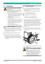
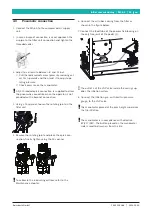
Fix the column to the cylinder tank by inserting
the pin with a hammer and tighten the fulcrum-pin
screw.
652012-07_Mi
4.
Insert again the pin passing through the cylinder
rod and tie rod holes; put back in place the external
elastic ring.
652012-08_Mi
5.
Connect the pneumatic lock supply pipe on the
pedal box joint.
652012-10_Mi
1
4.2.4
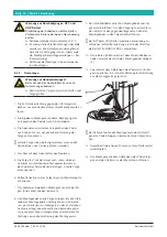
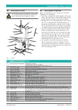
Put in place the vertical rod
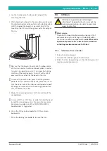
1.
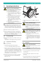
Put a hand down on the protection cap (placed on
top of the rod) and press it downwards; with the
other hand remove the steel rod inserted between
the arm and the mounting tool; take off slowly the
hand that was pressing the rod protection cap.
Danger!
The spring could eject violently the rod from
its housing, thus it might be a serious danger
for the operator.
Be careful when carrying out this operati-
on.
2.
Remove the adhesive tape with a cutter.
652012-09_Mi
4.2.5
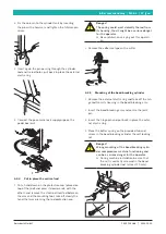
Mounting of the bead breaking cylinder
1.
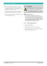
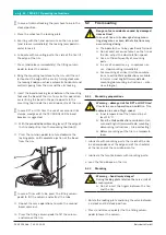
Remove the external elastic ring and take off the hin-
ge rod from its housing in the bead breaking arm.
2.
Insert the bead breaking arm and centre the joint
pin.
3.
Insert the hinge-pin and put back in place the exter-
nal elastic ring.
4.
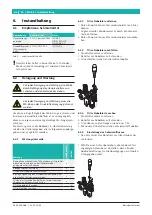
Place the buffer spring on the provided tab and
screw in the bead breaking cylinder the self locking
nut.
Danger!
Wrong mounting of the bead breaking cylin-
der compromises machine functioning and
can be a serious danger for the operator.
During machine installation be sure that
the nut is correctly screwed in the bead
breaking cylinder rod (at least 10 mm).
652012-11_Mi
Summary of Contents for MS 63
Page 2: ......
Page 21: ...1 695 106 288 2013 10 30 Beissbarth GmbH Technische Daten MS 63 21 de ...
Page 55: ...1 695 106 288 2013 10 30 Beissbarth GmbH Caractéristiques techniques MS 63 55 fr ...
Page 89: ...1 695 106 288 2013 10 30 Beissbarth GmbH Glossario MS 63 89 it ...
Page 155: ...1 695 106 288 2013 10 30 Beissbarth GmbH Dane techniczne MS 63 155 pl ...

