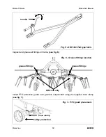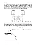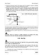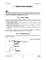
Install the two adjustable tine arms using M14x40 bolts and M14 nuts in the inner holes
of the tine arms and M14x25 socket head bolts in the outer holes.
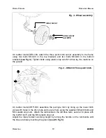
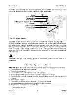
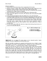
Assemble the left and right safety guards delivered with the machine
(see fig. 10)
.
On units equipped with the collapsible safety guards, bolt on the guard supports over
the safety guard support brackets using the supplied bolts and washers. Insert the
safety guards through the holes on each end of the guard supports and lock them in
place using the knobs. Safety guards need to be kept in the fully extended position
while the unit is in operation. Guards can be retracted for transport and storage
purposes only.
CAUTION: Always keep safety guards in extended position while unit is in
operation.
3.04 - Pre-Operational Check
IMPORTANT:
Check each of the following, carefully, prior to engaging the equipment:
1. The rotor bearings have been greased.
2. The oil in the gearbox.
3. The driveline cross and bearings have been greased.
4. No wrappings or foreign objects are around the tines or rotor flanges.
5. The tines are properly installed, the tine bolts properly torqued
4
and the timing is
correct.
6. All hardware is tight.
7. The tractor, to ensure correct direction of PTO and rpm speed.
8. All safety shields and guards are in place and tightly attached.
9. No people or animals are in the work area.
O
PERATION
16
BEFCO
R
OTARY
T
EDDERS
O
PERATOR
’
S
M
ANUAL
4
See Table 1, page 29.
Fig. 10 - Safety guards.
nut M12
safety guard support bracket
guard support
safety guard
knob
bolt M10x20
bolt M12x50
washer Ø12
Summary of Contents for DR0-330
Page 36: ......
Page 40: ...ROTARY TEDDERS RIGHT FRAME OPERATOR S MANUAL DR0 330 DRP 330 PARTS MANUAL 40 BEFCO 01 2012...
Page 54: ......

