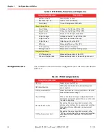
Configuration and Status
Chapter 4
9/3/21
Bedrock SPS.500 User Manual - BRDOC125_007
25
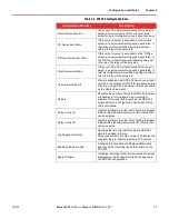
Total Overcurrent Limit
If the sum of the SPS outputs exceed this value (in
amps), an overcurrent condition will occur. See
below for more information on overcurrent behavior.
DC Overcurrent Warn
If this value (in amps) is exceeded on the primary
output, an overcurrent warning will be generated. If
the Output Overcurrent Warning flag is set for a
relay, the relay will be activated.
“OR”ing Overcurrent Warn
If this value (in amps) is exceeded on the “OR”ing
output, an overcurrent warning will be generated. If
the “OR”ing Output Overcurrent Warning flag is set
for a relay, the relay will be activated.
Total Overcurrent Warn
If the sum of the SPS outputs exceed this value (in
amps), an overcurrent warning will be generated. If
the Total Output Overcurrent Warning flag is set for a
relay, the relay will be activated.
Overcurrent Latch Off
When checked and the SPS.500 has an overcurrent
condition, the output will turn off for two seconds and
then turn on again for the number of times specified
by the Retries parameter.
Retries
Specifies the number of times the SPS.500 firmware
will attempt to turn on again in an overcurrent
situation. If the retry limit is reached, the SPS.500
output will remain off. Ignored if Overcurrent Latch
Off is unchecked.
Relay Control A
Use this pull
-
down to select which faults will activate
Relay A. See the table below for a list of faults that
can be selected.
Relay Control B
Use this pull
-
down to select which faults will activate
Relay B. See the table below for a list of faults that
can be selected.
Log Snapshot Interval
Specifies the time interval for capturing SPS.500
data to be added to the log.
Value is specified in minutes. Value of 0 disables the
snapshot feature. Maximum value is 720 minutes.
Enable setting date-time
Checking this checkbox will display editable date
and time fields for setting the date and time on the
SPS.500.
Apply Changes
If enabled, selecting this button will cause the values
displayed on the Configuration tab to be applied to
the SPS.500 configuration.
Table 4
-
2 SPS.500 Configuration Data
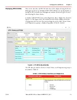
Group/Group Member
Description

