Chapter 1
Bedrock SPS.500 Overview
4
Bedrock SPS.500 User Manual - BRDOC125_007
9/3/21
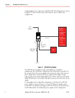
A wiring diagram for a typical non
-
redundant SPS.500 configuration is shown
in Figure 1
-
3. Note that the Power Out connector must be used in this
configuration.
Figure 1
-
3 SPS.500 Wiring Diagram
Two SPS.500 power supplies can be used together in a redundant
configuration. In a redundant configuration, the ORed output controller acts
like an ideal diode. The power supplies do not share the load so that only one
power supply carries the load. The power supply with the highest output
voltage carries the load. The Bedrock IDE or an OPC UA client can determine
which SPS.500 carries the load by checking the amount of current draw of each
supply.
A wiring diagram for a redundant configuration consisting of two SPS.500
power supplies is shown in Figure 1
-
4. The SPS.500 power supplies can be
connected to a workstation running an OPC UA client by way of an Ethernet
switch. Alternatively, the redundant power supplies can be configured to
Recommended
Fusing / Circuit
Breaker
Power
In
Power
Out
Recommended
Fusing / Circuit
Breaker
Relay
Output
(optional)
Et h er n et
AC Mains
Load
One of the
following:
x
Workstation
Running
OPC UA
x
Bedrock
SIO4.E comm.
module
x
UCG.5
x
OSA Remote


