Chapter 2
SPS.500 Installation
12
Bedrock SPS.500 User Manual - BRDOC125_007
9/3/21
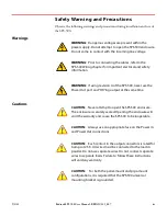
WARNING:
Prior to connecting the cables, refer to the SPS.500
Wiring chapter for important electrical and safety information.
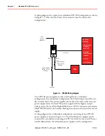
3. Connect the AC Power In cable, Power Out cable (
use the “OR”ing
out cable in a redundant configuration
), and the Relay cable
(optional) to the SPS.500. Connections are made as follows:
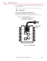
a. Align the Open arrow with the arrow on the mating connector and
then press together as shown in Figure 2-4.
Figure 2
-
4 Connector Alignment
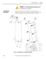
b. Rotate 1/4 turn clockwise to the locked position.
Figure 2
-
5 Locked Connector
Although a power cable is shown, the connection method applies to
all connections except for the Ethernet cable.


